ST7735
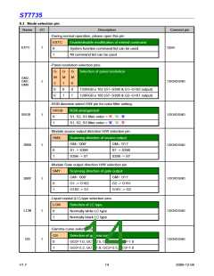
6.3 Mode selection pin
Name
I/O
Description
Connect pin
-During normal operation, please open this pin
EXTC
Enable/disable modification of extend command
EXTC
Open
I
0
1
System function command list can be used.
All command list can be used.
-Panel resolution selection pins.
G
M
2
G
M
1
G
M
0
Selection of panel resolution
GM2,
GM1,
GM0
VDDI/DGND
I
0
0
0
132RGB x 162 (S1~S396 & G1~G162 output)
128RGB x 160 (S7~S390 & G2~G161 output)
0
1
1
-RGB direction select H/W pin for color filter setting.
SRGB
RGB arrangement
SRGB
VDDI/DGND
I
I
0
1
S1, S2, S3 filter order = ’R’, ’G’, ’B’
S1, S2, S3 filter order = ‘B’, ‘G’, ‘R’
-Module source output direction H/W selection pin.
SMX
Scanning direction of source output
GM= ‘000’
S1 -> S396
S396 -> S1
GM= ‘011’
S7 -> S390
S390 -> S7
VDDI/DGND
SMX
0
1
-Module Gate output direction H/W selection pin.
SMY
Scanning direction of gate output
GM= ‘000’
G1 -> G162
G162 -> G1
GM= ‘011’
VDDI/DGND
SMY
I
0
1
G2 -> G161
G161 -> G2
-Liquid crystal (LC) type selection pins.
LCM
Selection of LC type
Normally white LC type
Normally black LC type
VDDI/DGND
VDDI/DGND
LCM
I
I
0
1
-Gamma curve selection pin.
GS
0
Selection of gamma curve
GS
GC0=1.0, GC1=2.5, GC2=2.2, GC3=1.8
GC0=2.2, GC1=1.8, GC2=2.5, GC3=1.0
1
V1.7
14
2009-12-04

 SITRONIX [ SITRONIX TECHNOLOGY CO., LTD. ]