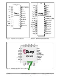
PIN NUMBER
SP3243EB
SOIC, SSOP, SP3243EBCR
NAME
FUNCTION
SP3223EB
TSSOP
QFN
EN
Receiver Enable. Apply logic LOW for normal operation.
1
-
-
Apply logic HIGH to disable the receiver outputs (high-Z state).
C1+
V+
Positive terminal of the voltage doubler charge-pump capacitor.
Regulated +5.5V output generated by the charge pump.
Negative terminal of the voltage doubler charge-pump capacitor.
Positive terminal of the inverting charge-pump capacitor.
Negative terminal of the inverting charge-pump capacitor.
Regulated -5.5V output generated by the charge pump.
RS-232 receiver input.
2
3
28
27
24
1
28
26
22
29
31
32
2
C1-
4
C2+
5
C2-
6
2
V-
7
3
R1IN
16
9
4
R2IN
RS-232 receiver input.
5
3
R3IN
RS-232 receiver input.
-
6
4
R4IN
RS-232 receiver input.
-
7
5
R5IN
RS-232 receiver input.
-
8
6
R1OUT
R2OUT
R2OUT
R3OUT
R4OUT
R5OUT
STATUS
T1IN
TTL/CMOS receiver output.
15
10
-
19
18
20
17
16
15
21
14
13
12
23
17
16
18
15
14
13
19
12
11
10
21
TTL/CMOS receiver output.
Non-inverting receiver-2 output, active in shutdown.
TTL/CMOS receiver output.
-
TTL/CMOS receiver output.
-
TTL/CMOS receiver output.
-
TTL/CMOS Output indicating online and shutdown status.
TTL/CMOS driver input.
11
13
12
-
T2IN
TTL/CMOS driver input.
T3IN
TTL/CMOS driver input.
ONLINE
Apply logic HIGH to override Auto-Online circuitry keeping
drivers active (SHUTDOWN must also be logic HIGH,
refer to Table 2).
14
T1OUT
T2OUT
T3OUT
GND
RS-232 driver output.
RS-232 driver output.
RS-232 driver output.
Ground.
17
8
9
7
8
10
11
25
26
22
-
9
18
19
20
23
25
20
VCC
+3.0V to +5.5V supply voltage.
SHUTDOWN Apply logic LOW to shut down drivers and charge pump.
This overrides all AUTO ON-LINE® circuitry and ONLINE
(refer to Table 2).
NC
No Connection
-
-
1,24,27,30
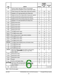
Table 1. Device Pin Description
Date: 6/2/04
SP3223EB/3243EB +3.0V to +5.5V RS-232 Transceivers
© Copyright 2004 Sipex Corporation
6

 SIPEX [ SIPEX CORPORATION ]