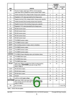
ELECTRICAL CHARACTERISTICS
Unless otherwise noted, the following specifications apply for VCC = +3.0V to +5.5V with TAMB = TMIN to TMAX
,
C1 - 4 = 0.1µF. Typical values apply at VCC = +3.3V or +5.0V and TAMB = 25°C.
PARAMETER
MIN.
TYP.
MAX. UNITS CONDITIONS
RECEIVER INPUTS
Input Voltage Range
Input Threshold LOW
Input Threshold LOW
Input Threshold HIGH
Input Threshold HIGH
Input Hysteresis
-25
0.6
0.8
25
V
V
1.2
1.5
1.5
1.8
0.3
5
VCC = 3.3V
VCC = 5.0V
VCC = 3.3V
VCC = 5.0V
V
2.4
2.4
V
V
V
Input Resistance
3
7
kΩ
®
AUTO ON-LINE CIRCUITRY CHARACTERISTICS (ONLINE = GND, SHUTDOWN = VCC
)
STATUS Output Voltage LOW
0.4
V
V
IOUT = 1.6mA
IOUT = -1.0mA
STATUS Output Voltage HIGH VCC - 0.6
Receiver Threshold to Drivers
Enabled (tONLINE
)
200
0.5
µs
µs
Figure 20
Figure 20
Receiver Positive or Negative
Threshold to STATUS HIGH
(tSTSH
)
Receiver Positive or Negative
Threshold to STATUS LOW
20
µs
Figure 20
(tSTSL
)
TIMING CHARACTERISTICS
Maximum Data Rate
250
kbps
RL = 3KΩ, CL = 1000pF,
one driver active
Receiver Propagation Delay
tPHL
tPLH
0.15
0.15
µs
Receiver input to Receiver output,
CL = 150pF
Receiver Output Enable Time
Receiver Output Disable Time
Driver Skew
200
200
100
50
ns
ns
Normal operation
Normal operation
ns
| tPHL - tPLH |, TAMB = 25°C
Receiver Skew
ns
| tPHL - tPLH |
Transition-Region Slew Rate
30
V/µs
VCC= 3.3V, RL = 3KΩ, TAMB = 25°C,
measurements taken from -3.0V to
+3.0V or +3.0V to -3.0V
Date: 6/2/04
SP3223EB/3243EB +3.0V to +5.5V RS-232 Transceivers
© Copyright 2004 Sipex Corporation
3

 SIPEX [ SIPEX CORPORATION ]