receiver's RXINACT signals with an accumu-
lated delay that disables the device to a 1µA
supply current.
®
AUTO ON-LINE Circuitry
The SP3223EB and SP3243EB devices have a
patent pending AUTO ON-LINE circuitry on
board that saves power in applications such as
laptop computers, palmtop (PDA) computers,
and other portable systems.
The STATUS pin goes to a logic LOW when the
cable is disconnected, the external transmitters
are disabled, or the SHUTDOWN pin is
invoked. The typical accumulated delay is
around 20µs.
®
TheSP3223EBandSP3243EBdevicesincorpo-
rate an AUTO ON-LINE circuit that automati-
When the SP3223EB and SP3243EB drivers or
internal charge pump are disabled, the supply
current is reduced to 1µA. This can commonly
occurinhand-heldorportableapplicationswhere
the RS-232 cable is disconnected or the RS-232
drivers of the connected peripheral are turned off.
®
cally enables itself when the external transmit-
ters are enabled and the cable is connected.
®
Conversely, the AUTO ON-LINE circuit also
disables most of the internal circuitry when the
device is not being used and goes into a standby
mode where the device typically draws 1µA.
This function can also be externally controlled
by the ONLINE pin. When this pin is tied to a
®
TheAUTOON-LINE modecanbedisabledby
theSHUTDOWNpin. IfthispinisalogicLOW,
®
the AUTO ON-LINE function will not operate
®
logic LOW, the AUTO ON-LINE function is
regardless of the logic state of the ONLINE pin.
Table 3 summarizes the logic of the AUTO ON-
active. Once active, the device is enabled until
there is no activity on the receiver inputs. The
receiver input typically sees at least ±3V, which
are generated from the transmitters at the other
end of the cable with a±5V minimum. When the
external transmitters are disabled or the cable is
disconnected, the receiver inputs will be pulled
down by their internal 5kΩ resistors to ground.
When this occurs over a period of time, the
internal transmitters will be disabled and the
device goes into a shutdown or standby mode.
®
LINE operatingmodes. Thetruthtablelogicof
the SP3223EB and SP3243EB driver and re-
ceiver outputs can be found in Table 2.
The STATUS pin outputs a logic LOW signal
if the device is shutdown. This pin goes to a
logic HIGH when the external transmitters are
enabled and the cable is connected.
When the SP3223EB and SP3243EB devices
are shut down, the charge pumps are turned off.
V+ charge pump output decays to VCC, the
V- output decays to GND. The decay time will
depend on the size of capacitors used for the
charge pump. Once in shutdown, the time
required to exit the shut down state and have
valid V+ and V- levels is typically 200µs.
®
WhenONLINEisHIGH,theAUTOON-LINE
mode is disabled.
®
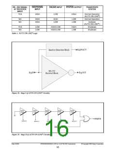
The AUTO ON-LINE circuit has two stages:
1) Inactive Detection
2) Accumulated Delay
The first stage, shown in Figure 28, detects an
inactive input. A logic HIGH is asserted on
RXINACT if the cable is disconnected or the
external transmitters are disabled. Otherwise,
RXINACT will be at a logic LOW. This circuit is
duplicated for each of the other receivers.
For easy programming, the STATUS can be
used to indicate DTR or a Ring Indicator signal.
Tying ONLINE and SHUTDOWN together
will bypass the AUTO ON-LINE circuitry so
this connection acts like a shutdown input pin.
®
®
The second stage of the AUTO ON-LINE cir-
cuitry, shown in Figure 29, processes all the
Date: 6/2/04
SP3223EB/3243EB +3.0V to +5.5V RS-232 Transceivers
© Copyright 2004 Sipex Corporation
17

 SIPEX [ SIPEX CORPORATION ]