EFR32MG13 Mighty Gecko Multi-Protocol Wireless SoC Family Data Sheet
Electrical Specifications
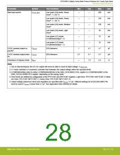
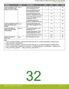
Parameter
Symbol
Test Condition
Min
Typ
Max
Unit
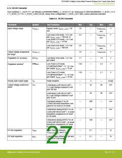
Max load current
ILOAD_MAX
Low noise (LN) mode, Heavy
Drive4, T ≤ 85 °C
—
—
200
mA
Low noise (LN) mode, Heavy
Drive4, T > 85 °C
—
—
—
—
—
1
—
—
—
—
—
4.7
100
100
50
mA
mA
mA
µA
Low noise (LN) mode, Medium
Drive4
Low noise (LN) mode, Light
Drive4
Low power (LP) mode,
LPCMPBIASEMxx3 = 0
75
Low power (LP) mode,
LPCMPBIASEMxx3 = 3
10
mA
µF
DCDC nominal output ca-
pacitor5
CDCDC
25% tolerance
4.7
DCDC nominal output induc- LDCDC
tor
20% tolerance
4.7
—
4.7
1.2
4.7
2.5
µH
Ω
Resistance in Bypass mode RBYP
Note:
1. Due to internal dropout, the DC-DC output will never be able to reach its input voltage, VVREGVDD
.
2. LP mode controller is a hysteretic controller that maintains the output voltage within the specified limits.
3. LPCMPBIASEMxx refers to either LPCMPBIASEM234H in the EMU_DCDCMISCCTRL register or LPCMPBIASEM01 in the
EMU_DCDCLOEM01CFG register, depending on the energy mode.
4. Drive levels are defined by configuration of the PFETCNT and NFETCNT registers. Light Drive: PFETCNT=NFETCNT=3; Medi-
um Drive: PFETCNT=NFETCNT=7; Heavy Drive: PFETCNT=NFETCNT=15.
5. Output voltage under/over-shoot and regulation are specified with CDCDC 4.7 µF. Different settings for DCDCLNCOMPCTRL
must be used if CDCDC is lower than 4.7 µF. See Application Note AN0948 for details.
silabs.com | Building a more connected world.
Rev. 1.4 | 28

 SILICON [ SILICON ]