EFR32MG13 Mighty Gecko Multi-Protocol Wireless SoC Family Data Sheet
Electrical Specifications
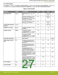
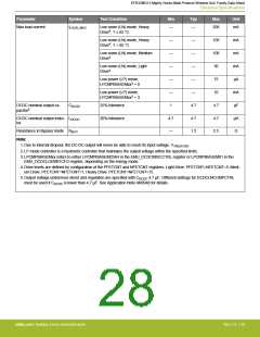
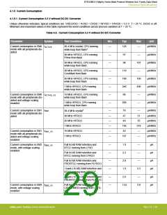
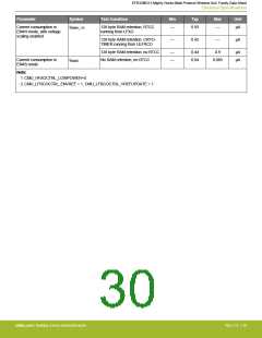
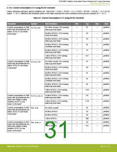
4.1.4 DC-DC Converter
Test conditions: L_DCDC=4.7 µH (Murata LQH3NPN4R7MM0L), C_DCDC=4.7 µF (Samsung CL10B475KQ8NQNC), V_DCDC_I=3.3
V, V_DCDC_O=1.8 V, I_DCDC_LOAD=50 mA, Heavy Drive configuration, F_DCDC_LN=7 MHz, unless otherwise indicated.
Table 4.4. DC-DC Converter
Parameter
Symbol
Test Condition
Min
Typ
Max
Unit
Input voltage range
VDCDC_I
Bypass mode, IDCDC_LOAD = 50
mA
1.8
—
VVREGVDD_
V
MAX
Low noise (LN) mode, 1.8 V out-
put, IDCDC_LOAD = 100 mA, or
Low power (LP) mode, 1.8 V out-
put, IDCDC_LOAD = 10 mA
2.4
—
VVREGVDD_
V
MAX
Low noise (LN) mode, 1.8 V out-
put, IDCDC_LOAD = 200 mA
2.6
1.8
—
—
VVREGVDD_
V
V
MAX
Output voltage programma- VDCDC_O
ble range1
VVREGVDD
Regulation DC accuracy
ACCDC
Low Noise (LN) mode, 1.8 V tar-
get output
1.7
—
—
1.9
2.2
V
V
Regulation window2
WINREG
Low Power (LP) mode,
LPCMPBIASEMxx3 = 0, 1.8 V tar-
get output, IDCDC_LOAD ≤ 75 µA
1.63
Low Power (LP) mode,
1.63
—
2.1
V
LPCMPBIASEMxx3 = 3, 1.8 V tar-
get output, IDCDC_LOAD ≤ 10 mA
Steady-state output ripple
VR
Radio disabled
—
—
3
—
mVpp
mV
CCM Mode (LNFORCECCM3 =
1), Load changes between 0 mA
and 100 mA
Output voltage under/over-
shoot
VOV
25
60
DCM Mode (LNFORCECCM3 =
0), Load changes between 0 mA
and 10 mA
—
45
90
mV
Overshoot during LP to LN
CCM/DCM mode transitions com-
pared to DC level in LN mode
—
—
200
40
—
—
mV
mV
Undershoot during BYP/LP to LN
CCM (LNFORCECCM3 = 1) mode
transitions compared to DC level
in LN mode
Undershoot during BYP/LP to LN
—
100
—
mV
DCM (LNFORCECCM3 = 0) mode
transitions compared to DC level
in LN mode
DC line regulation
DC load regulation
VREG
Input changes between
VVREGVDD_MAX and 2.4 V
—
—
0.1
0.1
—
—
%
%
IREG
Load changes between 0 mA and
100 mA in CCM mode
silabs.com | Building a more connected world.
Rev. 1.4 | 27

 SILICON [ SILICON ]