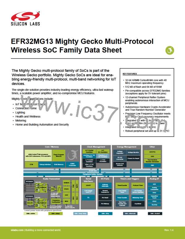
EFR32MG13 Mighty Gecko Multi-Protocol Wireless SoC Family Data Sheet
System Overview
3.5 Clocking
3.5.1 Clock Management Unit (CMU)
The Clock Management Unit controls oscillators and clocks in the EFR32MG13. Individual enabling and disabling of clocks to all periph-
erals is performed by the CMU. The CMU also controls enabling and configuration of the oscillators. A high degree of flexibility allows
software to optimize energy consumption in any specific application by minimizing power dissipation in unused peripherals and oscilla-
tors.
3.5.2 Internal and External Oscillators
The EFR32MG13 supports two crystal oscillators and fully integrates five RC oscillators, listed below.
• A high frequency crystal oscillator (HFXO) with integrated load capacitors, tunable in small steps, provides a precise timing refer-
ence for the MCU. Crystal frequencies in the range from 38 to 40 MHz are supported. An external clock source such as a TCXO can
also be applied to the HFXO input for improved accuracy over temperature.
• A 32.768 kHz crystal oscillator (LFXO) provides an accurate timing reference for low energy modes.
• An integrated high frequency RC oscillator (HFRCO) is available for the MCU system, when crystal accuracy is not required. The
HFRCO employs fast startup at minimal energy consumption combined with a wide frequency range.
• An integrated auxilliary high frequency RC oscillator (AUXHFRCO) is available for timing the general-purpose ADC and the Serial
Wire Viewer port with a wide frequency range.
• An integrated low frequency precision 32.768 kHz RC oscillator (PLFRCO) can be used as a timing reference in low energy modes,
with 500 ppm accuracy.
• An integrated low frequency 32.768 kHz RC oscillator (LFRCO) can be used as a timing reference in low energy modes, when crys-
tal accuracy is not required.
• An integrated ultra-low frequency 1 kHz RC oscillator (ULFRCO) is available to provide a timing reference at the lowest energy con-
sumption in low energy modes.
3.6 Counters/Timers and PWM
3.6.1 Timer/Counter (TIMER)
TIMER peripherals keep track of timing, count events, generate PWM outputs and trigger timed actions in other peripherals through the
PRS system. The core of each TIMER is a 16-bit counter with up to 4 compare/capture channels. Each channel is configurable in one
of three modes. In capture mode, the counter state is stored in a buffer at a selected input event. In compare mode, the channel output
reflects the comparison of the counter to a programmed threshold value. In PWM mode, the TIMER supports generation of pulse-width
modulation (PWM) outputs of arbitrary waveforms defined by the sequence of values written to the compare registers, with optional
dead-time insertion available in timer unit TIMER_0 only.
3.6.2 Wide Timer/Counter (WTIMER)
WTIMER peripherals function just as TIMER peripherals, but are 32 bits wide. They keep track of timing, count events, generate PWM
outputs and trigger timed actions in other peripherals through the PRS system. The core of each WTIMER is a 32-bit counter with up to
4 compare/capture channels. Each channel is configurable in one of three modes. In capture mode, the counter state is stored in a
buffer at a selected input event. In compare mode, the channel output reflects the comparison of the counter to a programmed thresh-
old value. In PWM mode, the WTIMER supports generation of pulse-width modulation (PWM) outputs of arbitrary waveforms defined by
the sequence of values written to the compare registers, with optional dead-time insertion available in timer unit WTIMER_0 only.
3.6.3 Real Time Counter and Calendar (RTCC)
The Real Time Counter and Calendar (RTCC) is a 32-bit counter providing timekeeping in all energy modes. The RTCC includes a
Binary Coded Decimal (BCD) calendar mode for easy time and date keeping. The RTCC can be clocked by any of the on-board oscilla-
tors with the exception of the AUXHFRCO, and it is capable of providing system wake-up at user defined instances. When receiving
frames, the RTCC value can be used for timestamping. The RTCC includes 128 bytes of general purpose data retention, allowing easy
and convenient data storage in all energy modes down to EM4H.
A secondary RTC is used by the RF protocol stack for event scheduling, leaving the primary RTCC block available exclusively for appli-
cation software.
silabs.com | Building a more connected world.
Rev. 1.4 | 13
