EFR32MG13 Mighty Gecko Multi-Protocol Wireless SoC Family Data Sheet
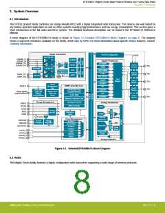
System Overview
3.3 Power
The EFR32MG13 has an Energy Management Unit (EMU) and efficient integrated regulators to generate internal supply voltages. Only
a single external supply voltage is required, from which all internal voltages are created. An optional integrated DC-DC buck regulator
can be utilized to further reduce the current consumption. The DC-DC regulator requires one external inductor and one external capaci-
tor.
The EFR32MG13 device family includes support for internal supply voltage scaling, as well as two different power domains groups for
peripherals. These enhancements allow for further supply current reductions and lower overall power consumption.
AVDD and VREGVDD need to be 1.8 V or higher for the MCU to operate across all conditions; however the rest of the system will
operate down to 1.62 V, including the digital supply and I/O. This means that the device is fully compatible with 1.8 V components.
Running from a sufficiently high supply, the device can use the DC-DC to regulate voltage not only for itself, but also for other PCB
components, supplying up to a total of 200 mA.
3.3.1 Energy Management Unit (EMU)
The Energy Management Unit manages transitions of energy modes in the device. Each energy mode defines which peripherals and
features are available and the amount of current the device consumes. The EMU can also be used to turn off the power to unused RAM
blocks, and it contains control registers for the DC-DC regulator and the Voltage Monitor (VMON). The VMON is used to monitor multi-
ple supply voltages. It has multiple channels which can be programmed individually by the user to determine if a sensed supply has
fallen below a chosen threshold.
3.3.2 DC-DC Converter
The DC-DC buck converter covers a wide range of load currents and provides up to 90% efficiency in energy modes EM0, EM1, EM2
and EM3, and can supply up to 200 mA to the device and surrounding PCB components. Patented RF noise mitigation allows operation
of the DC-DC converter without degrading sensitivity of radio components. Protection features include programmable current limiting,
short-circuit protection, and dead-time protection. The DC-DC converter may also enter bypass mode when the input voltage is too low
for efficient operation. In bypass mode, the DC-DC input supply is internally connected directly to its output through a low resistance
switch. Bypass mode also supports in-rush current limiting to prevent input supply voltage droops due to excessive output current tran-
sients.
3.3.3 Power Domains
The EFR32MG13 has two peripheral power domains for operation in EM2 and EM3. If all of the peripherals in a peripheral power do-
main are configured as unused, the power domain for that group will be powered off in the low-power mode, reducing the overall cur-
rent consumption of the device.
Table 3.1. Peripheral Power Subdomains
Peripheral Power Domain 1
Peripheral Power Domain 2
ACMP0
PCNT0
ADC0
ACMP1
CSEN
VDAC0
LEUART0
I2C0
LETIMER0
LESENSE
APORT
-
I2C1
IDAC
3.4 General Purpose Input/Output (GPIO)
EFR32MG13 has up to 31 General Purpose Input/Output pins. Each GPIO pin can be individually configured as either an output or
input. More advanced configurations including open-drain, open-source, and glitch-filtering can be configured for each individual GPIO
pin. The GPIO pins can be overridden by peripheral connections, like SPI communication. Each peripheral connection can be routed to
several GPIO pins on the device. The input value of a GPIO pin can be routed through the Peripheral Reflex System to other peripher-
als. The GPIO subsystem supports asynchronous external pin interrupts.
silabs.com | Building a more connected world.
Rev. 1.4 | 12

 SILICON [ SILICON ]