EFR32MG13 Mighty Gecko Multi-Protocol Wireless SoC Family Data Sheet
Typical Connection Diagrams
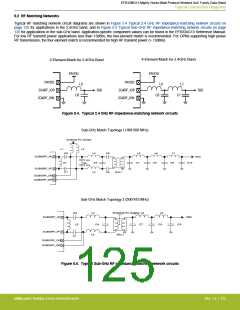
5.2 RF Matching Networks
Typical RF matching network circuit diagrams are shown in Figure 5.4 Typical 2.4 GHz RF impedance-matching network circuits on
page 125 for applications in the 2.4GHz band, and in Figure 5.5 Typical Sub-GHz RF impedance-matching network circuits on page
125 for applications in the sub-GHz band. Application-specific component values can be found in the EFR32xG13 Reference Manual.
For low RF transmit power applications less than 13dBm, the two-element match is recommended. For OPNs supporting high power
RF transmission, the four-element match is recommended for high RF transmit power (> 13dBm).
4-Element Match for 2.4GHz Band
2-Element Match for 2.4GHz Band
PAVDD
PAVDD
PAVDD
PAVDD
2G4RF_IOP
2G4RF_ION
L0
L0
L1
2G4RF_IOP
2G4RF_ION
50Ω
50Ω
C0
C0
C1
Figure 5.4. Typical 2.4 GHz RF impedance-matching network circuits
Sub-GHz Match Topology I (169-500 MHz)
External PA Supply
L1
L2
C0
L3
C5
L5
L6
L7
SUBGRF_IN
SUBGRF_IP
50Ω
C2
C3
C4
C7
C8
C9
C10
L0
C1
L4
C6
BAL1
SUBGRF_ON
SUBGRF_OP
Sub-GHz Match Topology 2 (500-915 MHz)
C0
L3
L5
L6
External PA Supply
SUBGRF_IN
50Ω
L0
C4
C7
C8
C9
SUBGRF_IP
L4
BAL1
C1
SUBGRF_ON
SUBGRF_OP
Figure 5.5. Typical Sub-GHz RF impedance-matching network circuits
silabs.com | Building a more connected world.
Rev. 1.4 | 125

 SILICON [ SILICON ]