EFM32G Data Sheet
Electrical Characteristics
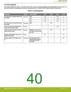
4.6 Power Management
The EFM32G requires the AVDD_x, VDD_DREG and IOVDD_x pins to be connected together (with optional filter) at the PCB level. For
practical schematic recommendations, please see the application note, "AN0002 EFM32 Hardware Design Considerations".
Table 4.5. Power Management
Parameter
Symbol
Test Condition
Min
1.74
1.74
1.74
—
Typ
—
Max
1.96
1.96
1.96
—
Unit
V
BOD threshold on falling external sup- VBODextthr- EM0
ply voltage
EM1
—
V
EM2
—
V
BOD threshold on rising external sup- VBODextthr+ EM0
ply voltage
1.85
V
Power-on Reset (POR) threshold on
rising external supply voltage
VPORthr+
—
—
—
1.98
—
V
Delay from reset is released until pro- tRESETdly
gram execution starts
Applies to Power-on Re-
set, Brown-out Reset and
pin reset.
163
µs
negative pulse length to ensure com-
plete reset of device
tRESET
50
—
—
1
—
—
ns
Voltage regulator decoupling capaci-
tor.
CDECOUPLE X5R capacitor recom-
mended. Apply between
DECOUPLE pin and
µF
GROUND
silabs.com | Building a more connected world.
Rev. 2.10 | 40

 SILICON [ SILICON ]