EFM32G Data Sheet
Pin Definitions
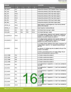
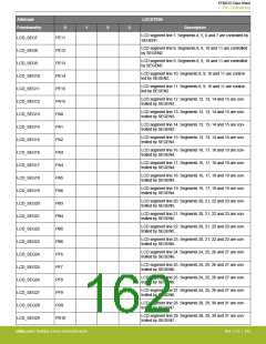
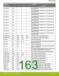
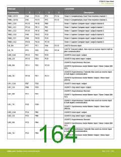
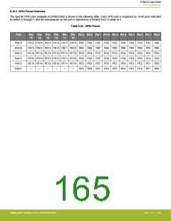
Alternate
LOCATION
Functionality
TIM0_CDTI1
TIM0_CDTI2
TIM1_CC0
TIM1_CC1
TIM1_CC2
TIM2_CC0
TIM2_CC1
TIM2_CC2
U0_RX
0
1
2
3
Description
PA4
PA5
PC14
PF4
PF5
PB0
PB1
PB2
PC8
PC9
PC14
Timer 0 Complimentary Deat Time Insertion channel 1.
Timer 0 Complimentary Deat Time Insertion channel 2.
Timer 1 Capture Compare input / output channel 0.
Timer 1 Capture Compare input / output channel 1.
Timer 1 Capture Compare input / output channel 2.
Timer 2 Capture Compare input / output channel 0.
Timer 2 Capture Compare input / output channel 1.
Timer 2 Capture Compare input / output channel 2.
UART0 Receive input.
PC15
PE10
PE11
PE12
PA12
PA13
PA14
PE1
PC15
PC13
PC14
PC15
PA8
PA9
PA10
PF7
PC10
PA4
PC15
PC14
UART0 Transmit output. Also used as receive input in half du-
plex communication.
U0_TX
PF6
PE0
PA3
US0_CLK
US0_CS
PE12
PE13
PE5
PE4
PC9
PC8
USART0 clock input / output.
USART0 chip select input / output.
USART0 Asynchronous Receive.
US0_RX
US0_TX
PE11
PE10
PE6
PE7
PC10
PC11
USART0 Synchronous mode Master Input / Slave Output (MI-
SO).
USART0 Asynchronous Transmit.Also used as receive input
in half duplex communication.
USART0 Synchronous mode Master Output / Slave Input
(MOSI).
US1_CLK
US1_CS
PB7
PB8
PD2
PD3
USART1 clock input / output.
USART1 chip select input / output.
USART1 Asynchronous Receive.
US1_RX
US1_TX
PC1
PC0
PD1
PD0
USART1 Synchronous mode Master Input / Slave Output (MI-
SO).
USART1 Asynchronous Transmit.Also used as receive input
in half duplex communication.
USART1 Synchronous mode Master Output / Slave Input
(MOSI).
US2_CLK
US2_CS
PC4
PC5
PB5
PB6
USART2 clock input / output.
USART2 chip select input / output.
USART2 Asynchronous Receive.
US2_RX
US2_TX
PC3
PC2
PB4
PB3
USART2 Synchronous mode Master Input / Slave Output (MI-
SO).
USART2 Asynchronous Transmit.Also used as receive input
in half duplex communication.
USART2 Synchronous mode Master Output / Slave Input
(MOSI).
silabs.com | Building a more connected world.
Rev. 2.10 | 164

 SILICON [ SILICON ]