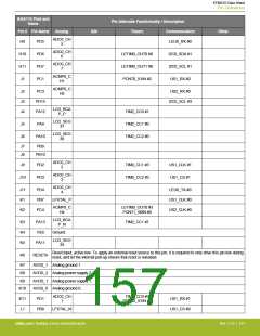
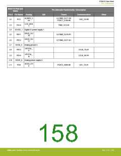
EFM32G Data Sheet
Pin Definitions
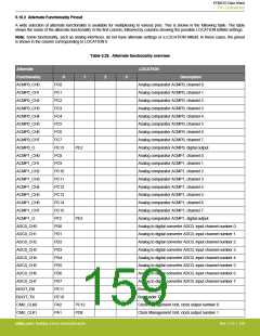
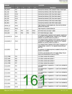
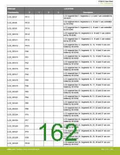
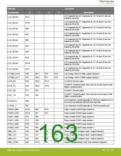
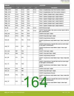
Alternate
Functionality
EBI_ARDY
EBI_CS0
EBI_CS1
EBI_CS2
EBI_CS3
EBI_REn
EBI_WEn
LOCATION
0
1
2
3
Description
PF2
PD9
External Bus Interface (EBI) Hardware Ready Control input.
External Bus Interface (EBI) Chip Select output 0.
External Bus Interface (EBI) Chip Select output 1.
External Bus Interface (EBI) Chip Select output 2.
External Bus Interface (EBI) Chip Select output 3.
External Bus Interface (EBI) Read Enable output.
External Bus Interface (EBI) Write Enable output.
PD10
PD11
PD12
PF5
PF4
High Frequency Crystal negative pin. Also used as external
optional clock input pin.
HFXTAL_N
PB14
HFXTAL_P
I2C0_SCL
I2C0_SDA
PB13
PA1
PA0
High Frequency Crystal positive pin.
I2C0 Serial Clock Line input / output.
I2C0 Serial Data input / output.
PD7
PD6
PC7
PC6
PD15
PD14
LCD voltage booster (optional), boost capacitor, negative pin.
If using the LCD voltage booster, connect a 22 nF capacitor
between LCD_BCAP_N and LCD_BCAP_P.
LCD_BCAP_N
LCD_BCAP_P
PA13
PA12
LCD voltage booster (optional), boost capacitor, positive pin.
If using the LCD voltage booster, connect a 22 nF capacitor
between LCD_BCAP_N and LCD_BCAP_P.
LCD voltage booster (optional), boost output. If using the LCD
voltage booster, connect a 1 uF capacitor between this pin
and VSS.
LCD_BEXT
PA14
An external LCD voltage may also be applied to this pin if the
booster is not enabled.
If AVDD is used directly as the LCD supply voltage, this pin
may be left unconnected or used as a GPIO.
LCD_COM0
LCD_COM1
LCD_COM2
LCD_COM3
PE4
PE5
PE6
PE7
LCD driver common line number 0.
LCD driver common line number 1.
LCD driver common line number 2.
LCD driver common line number 3.
LCD segment line 0. Segments 0, 1, 2 and 3 are controlled by
SEGEN0.
LCD_SEG0
LCD_SEG1
LCD_SEG2
LCD_SEG3
LCD_SEG4
LCD_SEG5
LCD_SEG6
PF2
PF3
PF4
PF5
PE8
PE9
PE10
LCD segment line 1. Segments 0, 1, 2 and 3 are controlled by
SEGEN0.
LCD segment line 2. Segments 0, 1, 2 and 3 are controlled by
SEGEN0.
LCD segment line 3. Segments 0, 1, 2 and 3 are controlled by
SEGEN0.
LCD segment line 4. Segments 4, 5, 6 and 7 are controlled by
SEGEN1.
LCD segment line 5. Segments 4, 5, 6 and 7 are controlled by
SEGEN1.
LCD segment line 6. Segments 4, 5, 6 and 7 are controlled by
SEGEN1.
silabs.com | Building a more connected world.
Rev. 2.10 | 161

 SILICON [ SILICON ]