C8051F52x-53x
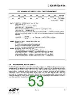
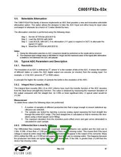
SFR Definition 5.6. ADC0TK: ADC0 Tracking Mode Select
R/W
Bit7
R/W
R/W
Bit5
R/W
Bit4
R/W
Bit3
R/W
Bit2
R/W
Bit1
R/W
Reset Value
11111111
SFR Address:
0xBA
AD0PWR
Bit6
AD0TM
AD0TK
Bit0
(bit addressable)
Bits7–4: AD0PWR3–0: ADC0 Burst Power-Up Time.
For BURSTEN = 0:
ADC0 power state controlled by AD0EN.
For BURSTEN = 1 and AD0EN = 1;
ADC0 remains enabled and does not enter the very low power state.
For BURSTEN = 1 and AD0EN = 0:
ADC0 enters the very low power state as specified in Table 5.1 and Table 5.2 and is enabled
after each convert start signal. The Power Up time is programmed according to the following
equation:
Tstartup
200ns
----------------------
AD0PWR =
– 1 or Tstartup = (AD0PWR + 1)200ns
Bits3–2: AD0TM1–0: ADC0 Tracking Mode Select Bits.
00: Reserved.
01: ADC0 is configured to Post-Tracking Mode.
10: ADC0 is configured to Pre-Tracking Mode.
11: ADC0 is configured to Dual-Tracking Mode (default).
Bits1–0: AD0TK1–0: ADC0 Post-Track Time.
Post-Tracking time is controlled by AD0TK as follows:
00: Post-Tracking time is equal to 2 SAR clock cycles + 2 FCLK cycles.
01: Post-Tracking time is equal to 4 SAR clock cycles + 2 FCLK cycles.
10: Post-Tracking time is equal to 8 SAR clock cycles + 2 FCLK cycles.
11: Post-Tracking time is equal to 16 SAR clock cycles + 2 FCLK cycles.
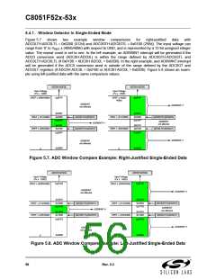
5.4. Programmable Window Detector
The ADC Programmable Window Detector continuously compares the ADC0 output registers to user-pro-
grammed limits, and notifies the system when a desired condition is detected. This is especially effective in
an interrupt-driven system, saving code space and CPU bandwidth while delivering faster system
response times. The window detector interrupt flag (AD0WINT in register ADC0CN) can also be used in
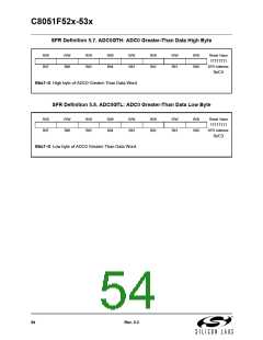
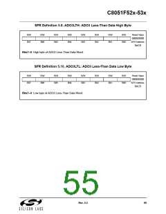
polled mode. The ADC0 Greater-Than (ADC0GTH, ADC0GTL) and Less-Than (ADC0LTH, ADC0LTL) reg-
isters hold the comparison values. The window detector flag can be programmed to indicate when mea-
sured data is inside or outside of the user-programmed limits, depending on the contents of the ADC0
Less-Than and ADC0 Greater-Than registers.
Rev. 0.3
53

 SILICON [ SILICON ]