C8051F52x-53x
20. Programmable Counter Array (PCA0)
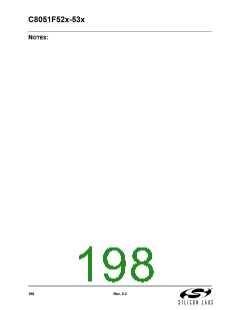
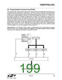
The Programmable Counter Array (PCA0) provides enhanced timer functionality while requiring less CPU
intervention than the standard 8051 counter/timers. The PCA consists of a dedicated 16-bit counter/timer
and three 16-bit capture/compare modules. Each capture/compare module has its own associated I/O line
(CEXn) which is routed through the Crossbar to Port I/O when enabled (See Section “14.1. Priority Cross-
bar Decoder” on page 119 for details on configuring the Crossbar). The counter/timer is driven by a pro-
grammable timebase that can select between six sources: system clock, system clock divided by four,
system clock divided by twelve, the external oscillator clock source divided by 8, Timer 0 overflow, or an
external clock signal on the ECI input pin. Each capture/compare module may be configured to operate
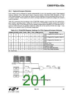
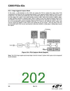
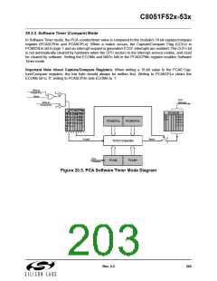
independently in one of three modes: Edge-Triggered Capture, Software Timer, High-Speed Output, Fre-
quency Output, 8-Bit PWM, or 16-Bit PWM (each mode is described in Section “20.2. Capture/Compare
Modules” on page 201). The PCA is configured and controlled through the system controller's Special
Function Registers. The PCA block diagram is shown in Figure 20.1
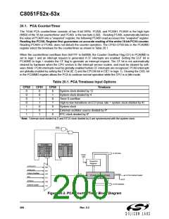
Important Note: The PCA Module 2 may be used as a watchdog timer (WDT), and is enabled in this mode
following a system reset. Access to certain PCA registers is restricted while WDT mode is enabled.
See Section “20.3. Watchdog Timer Mode” on page 207 for details.
SYSCLK/12
SYSCLK/4
Timer 0 Overflow
PCA
CLOCK
MUX
16-Bit Counter/Timer
ECI
SYSCLK
External Clock/8
Capture/Compare
Module 0
Capture/Compare
Module 1
Capture/Compare
Module 2
Crossbar
Port I/O
Figure 20.1. PCA Block Diagram
Rev. 0.3
199

 SILICON [ SILICON ]