C8051F52x-53x
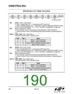
SFR Definition 19.2. TMOD: Timer Mode
R/W
GATE1
Bit7
R/W
C/T1
Bit6
R/W
T1M1
Bit5
R/W
T1M0
Bit4
R/W
GATE0
Bit3
R/W
C/T0
Bit2
R/W
T0M1
Bit1
R/W
T0M0
Reset Value
00000000
Bit0
SFR Address:
0x89
Bit7:
GATE1: Timer 1 Gate Control.
0: Timer 1 enabled when TR1 = 1 irrespective of /INT1 logic level.
1: Timer 1 enabled only when TR1 = 1 AND /INT1 is active as defined by bit IN1PL in regis-
ter IT01CF (see SFR Definition 11.5. “IT01CF: INT0/INT1 Configuration” on page 98).
C/T1: Counter/Timer 1 Select.
Bit6:
0: Timer Function: Timer 1 incremented by clock defined by T1M bit (CKCON.4).
1: Counter Function: Timer 1 incremented by high-to-low transitions on external input pin
(T1).
Bits5–4: T1M1–T1M0: Timer 1 Mode Select.
These bits select the Timer 1 operation mode.
T1M1
T1M0
Mode
0
0
1
1
0
1
0
1
Mode 0: 13-bit counter/timer
Mode 1: 16-bit counter/timer
Mode 2: 8-bit counter/timer with auto-reload
Mode 3: Timer 1 inactive
Bit3:
Bit2:
GATE0: Timer 0 Gate Control.
0: Timer 0 enabled when TR0 = 1 irrespective of /INT0 logic level.
1: Timer 0 enabled only when TR0 = 1 AND /INT0 is active as defined by bit IN0PL in regis-
ter IT01CF (see SFR Definition 11.5. “IT01CF: INT0/INT1 Configuration” on page 98).
C/T0: Counter/Timer Select.
0: Timer Function: Timer 0 incremented by clock defined by T0M bit (CKCON.3).
1: Counter Function: Timer 0 incremented by high-to-low transitions on external input pin
(T0).
Bits1–0: T0M1–T0M0: Timer 0 Mode Select.
These bits select the Timer 0 operation mode.
T0M1
T0M0
Mode
0
0
1
1
0
1
0
1
Mode 0: 13-bit counter/timer
Mode 1: 16-bit counter/timer
Mode 2: 8-bit counter/timer with auto-reload
Mode 3: Two 8-bit counter/timers
190
Rev. 0.3

 SILICON [ SILICON ]