STEP-DOWN, SYNCHRONOUS PWM CONTROL SWITCHING REGULATOR CONTROLLER
S-8533 Series
Rev.2.3_00
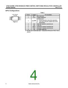
Pin Configurations
Table 1
8-Pin TSSOP
Top view
Pin No.
Symbol
NC*1
Pin Description
1
2
No connection
1
2
3
4
8
7
6
VOUT
Output voltage pin
Shutdown pin
H : Normal operation (step-down operation)
L : Step-down operation stopped (all circuits
deactivated)
5
3
ON/ OFF
Figure 2
4
5
6
7
8
CSS
VSS
Soft start capacitor connection pin
GND pin
NDRV
PDRV
VIN
External N-channel connection pin
External P-channel connection pin
IC power supply pin
*1. The NC pin is electrically open. Connection of this pin to VIN or VSS is
allowed.
4
Seiko Instruments Inc.

 SII [ SEIKO INSTRUMENTS INC ]