STEP-DOWN, SYNCHRONOUS PWM CONTROL SWITCHING REGULATOR CONTROLLER
Rev.2.3_00
S-8533 Series
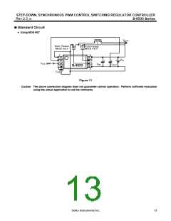
External Parts Selection
1. Inductor
The inductance value (L) greatly affects the maximum output current (IOUT) and the efficiency (η).
As the L value is reduced gradually, the peak current (IPK) increases, the stability of the circuit is improved, and IOUT
increases. As the L value is made even smaller, the efficiency is lowered, and IOUT decreases since the current
driveability of the switching transistor is insufficient.
As the L value is increased, the dissipation in the switching transistor due to IPK decreases, and the efficiency
reaches the maximum at a certain L value. As the L value is made even larger, the efficiency degrades since the
dissipation due to the series resistance of the coil increases. IOUT also decreases.
An inductance of 22 μH is recommended for the S-8533 Series.
When choosing an inductor, attention to its allowable current should be paid since the current exceeding the
allowable value will cause magnetic saturation in the inductor, leading to a marked decline in efficiency and the
breakdown of the IC due to large current.
An inductor should therefore be selected so that IPK does not surpass its allowable current. IPK is expressed by the
following equation :
V
OUT × (VIN − VOUT
)
IPK = IOUT +
2 × fOSC × L × VIN
where fOSC (= 300 kHz) is the oscillation frequency.
2. Capacitors (CIN, COUT
)
The capacitor (CIN) inserted on the input side serves to lower the power impedance, average input current, and
suppress back-flow current to the power source. Select the CIN value according to the impedance of the power
supplied, and select a capacitor that has low ESR (Equivalent Series Resistance) and large capacitance. It should
be approximately 47 to 100 μF, although the actual value depends on the impedance of the power source used and
load current value. When the input voltage is low and the load is large, the output voltage may become unstable.
In this case, increase the input capacitance.
For the output side capacitor (COUT), select a large capacitance with low ESR (Equivalent Series Resistance) to
smoothen the ripple voltage. When the input voltage is extremely high or the load current is extremely large, the
output voltage may become unstable. In this case, the unstable area will become narrow by selecting a large
capacitance for an output side capacitor. A tantalum electrolytic capacitor is recommended since the unstable area
widens when a capacitor with a large ESR, such as an aluminum electrolytic capacitor, or a capacitor with a small
ESR, such as a ceramic capacitor, is chosen. The range of the capacitance should generally be approximately 47
to 100 μF.
Fully evaluate input and output capacitors under the actual operating conditions to determine the best value.
Seiko Instruments Inc.
11

 SII [ SEIKO INSTRUMENTS INC ]