STEP-DOWN, SYNCHRONOUS PWM CONTROL SWITCHING REGULATOR CONTROLLER
S-8533 Series
Rev.2.3_00
Precautions
• Install the external capacitors, diode, coil, and other peripheral parts as close to the IC as possible, and make a one-
point grounding.
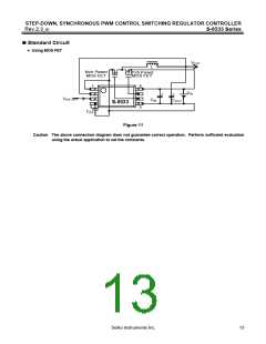
• Normally, the P-channel and N-channel MOS FETs do not turn ON at the same time. However, if the external P-
channel MOS FET has much different characteristics (input capacitance, Vth, etc.) from the external N-channel MOS
FET, they may turn ON at the same time, flowing a through current. Select P-channel and N-channel transistors with
similar characteristics.
• Characteristics ripple voltage and spike noise occur in IC containing switching regulators. Moreover rush current flows
at the time of a power supply injection. Because these largely depend on the coil, the capacitor and impedance of
power supply used, fully check them using an actually mounted model.
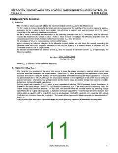
• If the input voltage is high and output current is low, pulses with a low duty ratio may be output, and then the duty ratio
may be 0% for several clocks.
• The PDRV and NDRV oscillation frequencies may be an integer fraction of 300 kHz at some input voltage and load
conditions. In this case, the ripple voltage may increase.
• The through current prevention circuit reduces through current by shifting the P-channel and N-channel transistor on
timing. It does not suppress the through current in the external transistors completely.
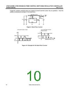
• Since PWM synchronous rectification is performed even when the load is light, current flows back to VIN. Check
whether the back-flow occurs and whether it affects the performance. (See “5. Back-Flow Current” in “
Operation”.)
• The PDRV or NDRV oscillation frequency may vary in a voltage range, depending on input voltage.
• When decreasing the power supply voltage slowly, the IC operation may be undefined if the voltage falls below the
minimum operating voltage.
• Make sure that dissipation of the switching transistor especially at high temperature will not surpass the power
dissipation of the package.
• Switching regulator performance varies depending on the design of PCB patterns, peripheral circuits and parts.
Thoroughly evaluate the actual device when setting. When using parts other than those which are recommended,
contact the SII marketing department.
• Do not apply an electrostatic discharge to this IC that exceeds the performance ratings of the built-in electrostatic
protection circuit.
• SII claims no responsibility for any disputes arising out of or in connection with any infringement by products including
this IC of patents owned by a third party.
14
Seiko Instruments Inc.

 SII [ SEIKO INSTRUMENTS INC ]