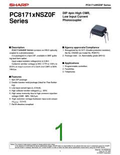
PC8171xNSZ0F Series
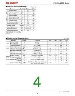
■ Absolute Maximum Ratings
(Ta=25˚C)
Unit
mA
mA
V
Parameter
Symbol
IF
Rating
Forward current
10
*1 Peak forward current
Reverse voltage
IFM
200
VR
6
Power dissipation
P
15
mW
V
Collector-emitter voltage
Emitter-collector voltage
Collector current
VCEO
VECO
IC
80
6
50
V
mA
mW
mW
kV
Collector power dissipation
Total power dissipation
*2 Isolation voltage
Operating temperature
Storage temperature
*3 Soldering temperature
PC
150
Ptot
170
Viso (rms)
Topr
Tstg
Tsol
5.0
−30 to +100
−55 to +125
260
˚C
˚C
˚C
*1 Pulse width≤100µs, Duty ratio : 0.001
*2 40 to 60%RH, AC for 1 minute, f=60Hz
*3 For 10s
■ Electro-optical Characteristics
(Ta=25˚C)
Parameter
Forward voltage
Symbol
VF
Conditions
MIN.
TYP.
MAX.
1.4
10
Unit
V
IF=10mA
VR=4V
−
1.2
Input Reverse Current
Terminal capacitance
Collector dark current
IR
−
−
µA
pF
nA
V
Ct
V=0, f=1kHz
−
30
250
100
−
ICEO
VCE=50V, IF=0
IC=0.1mA, IF=0
IE=10µA, IF=0
IF=0.5mA, VCE=5V
IF=10mA, IC=1mA
DC500V, 40 to 60%RH
V=0, f=1MHz
−
−
Output Collector-emitter breakdown voltage BVCEO
80
−
Emitter-collector breakdown voltage
BVECO
IC
6
−
−
V
Collector current
0.5
−
3.0
0.2
−
mA
V
Collector-emitter saturation voltage VCE (sat)
−
−
1×10¹¹
0.6
4
Isolation resistance
Floating capacitance
RISO
Cf
tr
5×10¹⁰
Ω
Transfer
charac-
teristics
−
−
−
1.0
18
pF
µs
µs
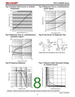
Rise time
Response time
VCE=2V, IC=2mA, RL=100Ω
Fall time
tf
3
18
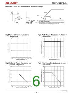
Ta=25˚C, RL=470Ω, VCM=1.5kV(peak)
IF=0, VCC=9V, Vnp=100mV
Common mode rejection voltage
CMR
10
−
−
kV/µs
Sheet No.: D2-A03302FEN
4

 SHARP [ SHARP ELECTRIONIC COMPONENTS ]