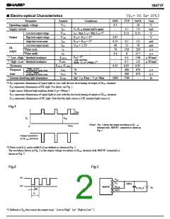
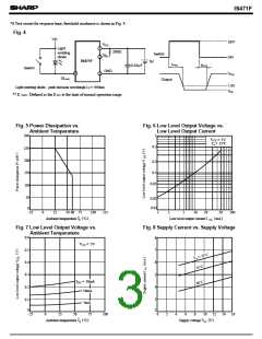
IS471F
( )
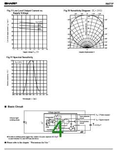
Fig.10 Sensitivity Diagram Ta = 25˚C
Fig. 9 Low Level Output Current vs.
Supply Voltage
80
0˚
100
-20˚
-10˚
+10˚
+20˚
70
- 30˚
- 40˚
+30˚
80
60
40
20
Ta =-25˚C
60
25˚C
50
+40˚
+50˚
60˚C
40
30
20
10
0
- 50˚
- 60˚
+60˚
+70˚
- 70˚
- 80˚
- 90˚
+80˚
+90˚
2
4
6
8
10
12
14
16
18
0
(
)
Supply voltage V cc
V
Angular displacement θ
Fig.11 Spectral Sensitivity
100
Ta = 25˚C
90
80
70
60
50
40
30
20
10
0
400 500 600 700 800 900 1000 1100 1200 1300 1400
(
)
Wavelength λ nm
■ Basic Circuit
Voltage regulator
(
)
Vcc Power supply
Sync.detector
circuit
Comparator
Infrared light
emitting diode
(
)
Vo Signal output
Demodulator
circuit
❈
C = 0.33µ F
Amp.
Oscillator
❈ In order to stabilize power supply line, connect a by-pass capacitor of 0.33µF
or more between Vcc and GNP near the device.
● Please refer to the chapter “Precautions for Use.”

 SHARP [ SHARP ELECTRIONIC COMPONENTS ]