SX1231
ADVANCED COMMUNICATIONS & SENSING
DATASHEET
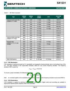
The following table summarizes the performance (typical figures) of the complete receiver:
Table 12 Receiver Performance Summary
Input Power
Pin
Gain
Setting
Receiver Performance (typ)
P-1dB
[dBm]
-37
NF
IIP3
IIP2
[dBm]
[dB]
[dBm]
Pin < AgcThresh1
G1
G2
G3
G4
G5
G6
7
-18
-15
-8
+35
+40
+48
+62
+68
+75
AgcThresh1 < Pin < AgcThresh2
AgcThresh2 < Pin < AgcThresh3
AgcThresh3 < Pin < AgcThresh4
AgcThresh4 < Pin < AgcThresh5
AgcThresh5 < Pin
-31
13
18
27
36
44
-26
-14
-1
>-6
+13
+20
>0
3.5.3.1. RssiThreshold Setting
For correct operation of the AGC, RssiThreshold in RegRssiThresh must be set to the sensitivity of the receiver. The
receiver will remain in WAIT mode until RssiThreshold is exceeded.
3.5.3.2. AGC Reference Setting
By default, the AGC reference level is automatically computed (AgcAutoReferenceOn = 1), according to:
AGC Reference [dBm] = -174 + NF + DemodSnr +10.log(2*RxBw) + AgcSnrMargin [dBm]
With:
NF = 7dB:
LNA’s Noise Figure at maximum gain
DemodSnr = 8 dB: SNR needed by the demodulator
RxBw:
Single sideband channel filter bandwidth
AgcSnrMargin:
in dB, set in RegAgcThresh1
Fading margin can be adjusted through AgcSnrMargin. Sufficient margin must be taken to ensure reliable operation of the
SX1231 receiver, when the incoming signal level during the RSSI evaluation (WAIT mode) is close to AgcThresh1.
Note When the AGC reference level is manually set by the user (AgcAutoReferenceOn=0) with AgcReferenceLevel in
RegAgcRef, the user should manually account for its optimal fading margin.
3.5.4. Quadrature Mixer - ADCs - Decimators
The mixer is inserted between output of the RF buffer stage and the input of the analog to digital converter (ADC) of the
receiver section. This block is designed to translate the spectrum of the input RF signal to base-band, and offer both high
IIP2 and IIP3 responses.
In the lower bands of operation (290 to 510 MHz), the multi-phase mixing architecture with weighted phases improves the
rejection of the LO harmonics in receiver mode, hence increasing the receiver immunity to out-of-band interferers.
th
The I and Q digitalization is made by two 5 order continuous-time Sigma-Delta Analog to Digital Converters (ADC). Their
gain is not constant over temperature, but the whole receiver is calibrated before reception, so that this inaccuracy has no
Rev 2 - Nov 2009
Page 24
www.semtech.com

 SEMTECH [ SEMTECH CORPORATION ]