SX1231
ADVANCED COMMUNICATIONS & SENSING
DATASHEET
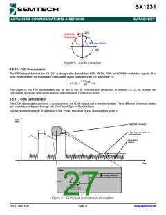
The current consumption of the LNA can be reduced at the expense of its performance by setting the bit LnaLowPowerOn
in RegLna. In the same way the consumption of the AD converter can be reduced by setting AdcLowPowerOn in
RegTemp1.
3.5.3. Automatic Gain Control
By default (LnaGainSelect = 000), the LNA gain is controlled by a digital AGC loop in order to obtain the optimal sensitivity/
linearity trade-off.
Regardless of the data transfer mode (Packet or Continuous), the following series of events takes place when the receiver
is enabled:
The receiver stays in WAIT mode, until RssiValue exceeds RssiThreshold for two consecutive samples. Its power
consumption is the receiver power consumption.
When this condition is satisfied, the receiver automatically selects the most suitable LNA gain, optimizing the sensitivity/
linearity trade-off.
The programmed LNA gain, read-accessible with LnaCurrentGain in RegLna, is carried on for the whole duration of the
packet, until one of the following conditions is fulfilled:
Packet mode: if AutoRxRestartOn = 0, the LNA gain will remain the same for the reception of the following packet. If
AutoRxRestartOn = 1, after the controller has emptied the FIFO the receiver will re-enter the WAIT mode described
above, after a delay of InterPacketRxDelay, allowing for the distant transmitter to ramp down, hence avoiding a false
RSSI detection.
Continuous mode: upon reception of valid data, the user can decide to either leave the receiver enabled with the same
LNA gain, or to restart the procedure, by setting RestartRx bit to 1, resuming the WAIT mode of the receiver, described
above.
Notes - the first RSSI sample exceeding RssiThreshold must be confirmed by a second one sample, unless FastRx in
RegRssiConfig is set to 1.
- the AGC procedure must be performed while receiving preamble in FSK mode
- in OOK mode, the AGC will give better results if performed while receiving a constant “1” sequence
The following figure illustrates the different AGC settings available in the registers RegAgcRef, RegAgcThresh1 and
RegAgcThresh2:
Towards
-125 dBm
AgcStep1
AgcStep2
AgcStep3
AgcStep4
AgcStep5
Pin [dBm]
G1
G2
G3
G4
G5
G6
Higher Sensitivity
Lower Linearity
Lower Sensitivity
Higher Linearity
Lower Noise Figure
Higher Noise Figure
Figure 7. AGC Thresholds Settings
AgcStep settings can be user modified in both Automatic and Manual AgcReference modes, but the default values give
good results.
Rev 2 - Nov 2009
Page 23
www.semtech.com

 SEMTECH [ SEMTECH CORPORATION ]