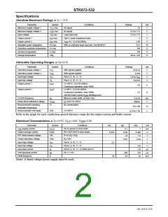
STK672-532
Precautions
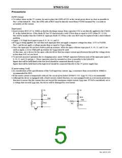
[GND wiring]
• To reduce noise on the 5V system, be sure to place the GND of C01 in the circuit given above as close as possible to
Pin 1 of the hybrid IC. Also, the GND side of RO2 must be directly wired from P.GND terminal Pin 1 in order to
accurately set the current.
[Input pins]
• Insert resistor RO3 (47 to 100Ω) so that the discharge energy from capacitor CO2 is not directly applied to the CMOS
IC in this hybrid device. If the diode D1 has Vf characteristics with Vf less than or equal to 0.6V (when If = 0.1A),
this will be smaller than the CMOS IC input pin diode Vf. If this is the case RO3 may be replaced with a short without
problem.
• Apply 2.5V High level input to pins 8, 9, 10, 11, and 12.
• If V
is being applied, use care that each input pin does not apply a negative voltage less than -0.3V to P.GND,
DD
Pin 1, and do not apply a voltage greater than or equal to V
voltage.
DD
• Since the input pins do not have built-in pull-up resistors, when the open-collector type pins 8, 9, 10, 11, and 12 are
used as inputs, a 10 to 47kΩ pull-up resistor (to V ) must be used.
DD
At this time, use a device for the open collector driver that has output current specifications that pull the voltage down
to less than 0.6V at Low level.
• To prevent incorrect operation due to chopping noise, insert 1000pF capacitors between each of the input pins (pins 8,
9, 10, 11 and 12) and pin 1. These capacitors must be mounted as close as possible to the hybrid IC.
Inputs that will be held fixed at the low level should be connected directly to pin 1.
Inputs that will be held fixed at the high level should be connected directly to the 5V power supply line.
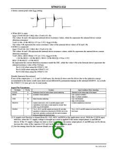
[Current setting Vref]
• In consideration of the specifications of the Vref input bias current, I , a resistance from several kΩ to 100kΩ is
IB
recommended for RO1.
• If the motor current is temporarily reduced, the circuit given below (STK672-532: I >0.17A) is recommended.
OH
• Although the driver is equipped with a fixed current control function, it is not equipped with an overcurrent protection
function to ensure that the current does not exceed the maximum output current, I
max. If Vref is mistakenly set to
OH
a voltage that exceeds I
max, the driver will be damaged by overcurrent.
OH
5V
5V
RO1
Vref
RO1
Vref
RO2
R3
R3
RO2
No. A2111-5/23

 SANYO [ SANYO SEMICON DEVICE ]