STK672-532
2. Calculating STK672-532 HIC Internal Power Loss
The average internal power loss in each excitation mode of the STK672-532 can be calculated from the following
formulas.
Each excitation mode
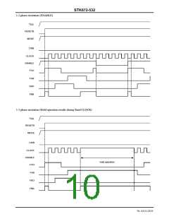
2-phase excitation mode
2PdAVex= (Vsat+Vdf) ×0.5×CLOCK×I ×t2+0.5×CLOCK×I × (Vsat×t1+Vdf×t3)
OH OH
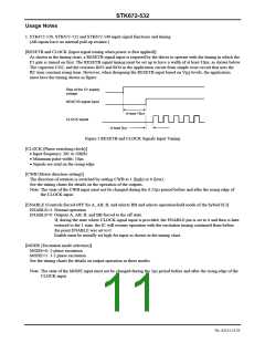
1-2 phase excitation mode
1-2PdAVex= (Vsat+Vdf) ×0.25×CLOCK×I ×t2+0.25×CLOCK×I × (Vsat×t1+Vdf×t3)
OH OH
Motor hold mode
HoldPdAVex= (Vsat+Vdf) ×I
OH
Vsat: Combined voltage represented by the Ron voltage drop+shunt resistor
Vdf: Combined voltage represented by the MOSFET body diode+shunt resistor
CLOCK: Input CLOCK (CLOCK pin signal frequency)
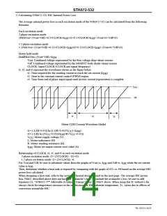
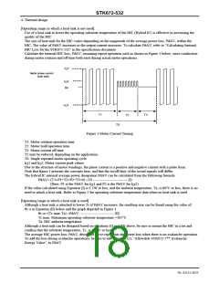
t1, t2, and t3 represent the waveforms shown in the figure below.
t1: Time required for the winding current to reach the set current (I
t2: Time in the constant current control (PWM) region
)
OH
t3: Time from end of phase input signal until inverse current regeneration is complete
I
OH
0A
t1
t2
t3
Motor COM Current Waveform Model
t1= (-L/(R+0.45)) ln (1-((R+0.45)/V ) ×I
CC OH
)
t3= (-L/R) ln ((V +0.45)/(I ×R+V +0.45))
CC OH CC
: Motor supply voltage (V)
CC
L: Motor inductance (H)
V
R: Motor winding resistance (Ω)
I
: Motor set output current crest value (A)
OH
Relationship of CLOCK, t1, t2, and t3 in each excitation mode
2-phase excitation mode: t2= (2/CLOCK) - (t1+t3)
1-2 phase excitation mode: t2= (3/CLOCK) -t1
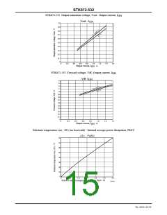
For Vsat and Vdf, be sure to substitute values from the graphs of Vsat vs. I
and Vdf vs. I
while the set current
OH
OH
value is I
.
OH
Then, determine whether a heat sink is required by comparing with the graph of ΔTc vs. Pd based on the average HIC
power loss calculated.
When designing a heat sink, refer to the section “Thermal design” found on the next page. The average HIC power
loss, PdAV, described above does not have the avalanche’s loss. To include the avalanche’s loss, be sure to add
Equation (2), “STK672-5** Allowable Avalanche Energy Value” to PdAV above. When using this IC without a fin
always check for temperature increases in the set, because the HIC substrate temperature, Tc, varies due to effects of
convection around the HIC.
No. A2111-14/23

 SANYO [ SANYO SEMICON DEVICE ]