STK672-532
3. STK672-532 Allowable Avalanche Energy Value
(1) Allowable Range in Avalanche Mode
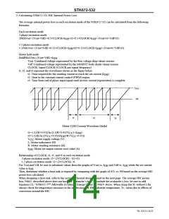
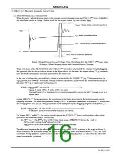
When driving a 2-phase stepping motor with constant current chopping using an STK672-5** Series hybrid IC,
the waveforms shown in Figure 1 below result for the output current, I , and voltage, V
.
DS
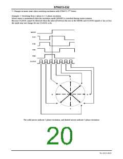
D
V
: Voltage during avalanche operations
DSS
V
DS
I
: Motor current peak value
OH
IAVL: Current during avalanche operations
I
D
tAVL: Time of avalanche operations
ITF02557
Figure 1 Output Current, I , and Voltage, V , Waveforms 1 of the STK672-5** Series when
DS
D
Driving a 2-Phase Stepping Motor with Constant Current Chopping
When operations of the MOSFET built into STK672-5** Series ICs is turned off for constant current chopping,
the I signal falls like the waveform shown in the figure above. At this time, the output voltage, V , suddenly
D
DS
rises due to electromagnetic induction generated by the motor coil.
In the case of voltage that rises suddenly, voltage is restricted by the MOSFET V
. Voltage restriction by
DSS
V
results in a MOSFET avalanche. During avalanche operations, I flows and the instantaneous energy at
D
DSS
this time, EAVL1, is represented by Equation (1).
EAVL1=V
V
×IAVL×0.5×tAVL ------------------------------------------- (1)
DSS
: V units, IAVL: A units, tAVL: sec units
DSS
The coefficient 0.5 in Equation (1) is a constant required to convert the IAVL triangle wave to a
square wave.
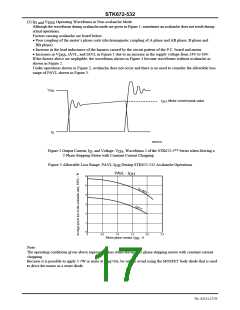
During STK672-5** Series operations, the waveforms in the figure above repeat due to the constant current
chopping operation. The allowable avalanche energy, EAVL, is therefore represented by Equation (2) used to find
the average power loss, PAVL, during avalanche mode multiplied by the chopping frequency in Equation (1).
PAVL=V
×IAVL×0.5×tAVL×fc ------------------------------------------- (2)
fc: Hz units (fc is set to the PWM frequency of 50kHz.)
DSS
For V
DSS
, IAVL, and tAVL, be sure to actually operate the STK672-5** Series and substitute values when
operations are observed using an oscilloscope.
Ex. If V =110V, IAVL=1A, tAVL=0.2μs when using a STK672-532 driver, the result is:
DSS
PAVL=110×1×0.5×0.2×10-6×50×103=0.55W
=110V is a value actually measured using an oscilloscope.
V
DSS
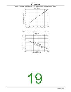
The allowable loss range for the allowable avalanche energy value, PAVL, is shown in the graph in Figure 3.
When examining the avalanche energy, be sure to actually drive a motor and observe the I , V , and tAVL
D
DSS
waveforms during operation, and then check that the result of calculating Equation (2) falls within the allowable
range for avalanche operations.
No. A2111-16/23

 SANYO [ SANYO SEMICON DEVICE ]