LC89057W-VF4A-E
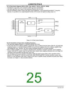
10.3.4 Data block diagram (RX0 to RX6, TX0, RXOUT, TDATA, RDATA, SDIN)
•
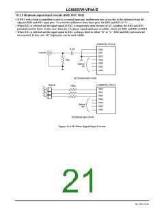
The RDATA output data can be switched to SDIN input data with RDTSEL.
•
The SDIN input data can be input to the modulation function with TDTSEL.
•
Since the modulation output is input to the input switch multiplexer, it can be fetched from RXOUT. Using this
function, it is possible to use a signal digitized with the A/D converter for digital recording output, etc.
SDIN
[RDTSEL]
RX0
RDATA
MUX
(8in / 2out)
RX1
DIR
RX2
RX3
RX4
RX5
RX6
RXOUT
TXO
[TDTSEL]
DIT
TDATA
Figure 10.10 Data System Diagram
10.3.5 Calculation of input data sampling frequency
•
The input data sampling frequency is calculated using the XIN clock.
•
In the mode where the oscillation amplifier automatically stops according to the lock status of the PLL, the input data
sampling frequency is calculated during the RERR error period and completed when the oscillation amplifier stops
with holding the value. Therefore, the value remains unchanged until the PLL becomes unlocked.
If the oscillation amplifier is in a continuous operation mode, calculation is repeated constantly. Even if sampling
changes within the PLL capture range for input data whose channel status sampling information does not change, the
calculation results that follow the input data can be read.
The calculation result can be read from CCB address 0xEB and output registers DO4 to DO7 and DO8 to DO15.
Registers DO4 through DO7 hold the encoded result, while DO8 through DO15 hold the calculated counter value.
However, as the calculation count value is output in 8 bit units, fs capable of being calculated are greater than 24kHz.
For details, see Chapter 12. Microcontroller Interface.
•
•
No.7202-25/59

 SANYO [ SANYO SEMICON DEVICE ]