LC866548/40/32/28/24A
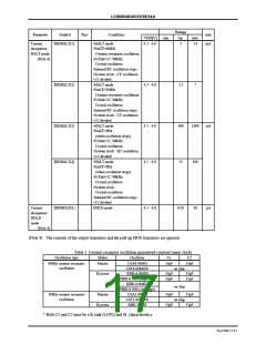
Ratings
typ.
Parameter
Symbol
Pins
Conditions
VDD[V]
unit
mA
min.
max.
14
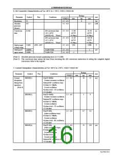
Current
IDDHALT(1)
•HALT mode
4.5 - 6.0
5
dissipation
HALT mode
(Note 4)
•FmCF=6MHz
Ceramic resonator oscillation
•FsXtal=32.768kHz
Crystal oscillation
•Internal RC oscillation stops.
•System clock : CF oscillation
•1/1 divided
IDDHALT(2)
•HALT mode
4.5 - 6.0
2.2
7
•FmCF=3MHz
Ceramic resonator oscillation
•FsXtal=32.768kHz
Crystal oscillation
•Internal RC oscillation stops.
•System clock : CF oscillation
•1/2 divided
IDDHALT(3)
IDDHALT(4)
•HALT mode
4.5 - 6.0
400
1600
µA
•FmCF=0Hz
(when oscillation stops)
•FsXtal=32.768kHz
Crystal oscillation
•System clock : RC oscilaltion
•1/2 divided
•HALT mode
4.5 - 6.0
25
100
•FmCF=0Hz
(when oscillation stops)
•FsXtal=32.768kHz
Crystal oscillation
•System clock :
Crystal oscilaltion
•Internal RC oscillation stops.
•1/2 divided
Current
dissipation
HOLD
IDDHOLD(1)
HOLD mode
4.5 - 6.0
0.05
30
µA
mode
(Note 4)
(Note 4) The currents of the output transistors and the pull-up MOS transistors are ignored.
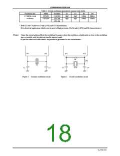
Table 1. Ceramic resonator oscillation guaranteed constant (main clock)
Oscillation type
Maker
Oscillator
CSA6.00MG
C1
C2
6MHz ceramic resonator
oscillation
Murata
33pF
33pF
CST6.00MGW
KBR-6.0MSB
on chip
Kyocera
33pF
33pF
33pF
33pF
PBRC6.00A (chip type)
KBR-6.0MKC
on chip
on chip
PBRC6.00B (chip type)
CSA3.00MG
3MHz ceramic resonator
oscillation
Murata
33pF
33pF
33pF
33pF
CST3.00MGW
KBR-3.0MS
Kyocera
* Both C1 and C2 must be a K rank (±10%) and SL characteristics.
No.6700-17/21

 SANYO [ SANYO SEMICON DEVICE ]