LC786960E
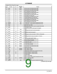
Continued from the previous page.
Pin
State when
"Reset"
Pin name
GP30
I/O
Function
No.
47
I/O
I/O
Input (L)
Input (L)
General purpose I/O port with pull down resistor
General purpose I/O port with pull down resistor
48
GP31
GP32
General purpose I/O port with pull down resistor
Data 1 input/output for SD memory card
General purpose I/O port with pull down resistor
Data 0 input/output for SD memory card
General purpose I/O port with pull down resistor
Clock output for SD memory card
49
50
51
52
53
54
I/O
I/O
I/O
I/O
I/O
I/O
Input (L)
Input (L)
Input (L)
Input (L)
Input (L)
Input (L)
GP33
GP34
GP35
GP36
GP37
General purpose I/O port with pull down resistor
Command input/output for SD memory card
General purpose I/O port with pull down resistor
Data 3 input/output for SD memory card
General purpose I/O port with pull down resistor
Data 2 input/output for SD memory card
55
56
57
58
MODE0
MODE1
I
I
Input
LSI mode set pin 0 This pin must be connected to the 0V level.
LSI mode set pin 1 This pin must be connected to the 0V level.
Digital system power supply
Input
DV
DD
-
-
-
-
DV
SS
Digital system ground. This pin must be connected to the 0V level.
IC reset input ("L"-active)
59
60
61
62
63
64
65
66
67
RESB
SIFCK
SIFDI
SIFDO
SIFCE
BUSYB
GP03
GP04
GP05
I
-
This pin must be set low once after power is first applied.
Host-I/F
I
Input
Data transmit clock input for serial communication 1
Host-I/F
I/O
I/O
I/O
I/O
I/O
I/O
I/O
Input
Data input for serial communication 1
Host-I/F
Input
Data output for serial communication 1 (CMOS or 3-State output)
Host -I/F
Input
Enable signal input for serial communication 1 ("H"-active)
Host -I/F
Input (L)
Input (L)
Input (L)
Input (L)
System busy signal output ("L"-active)
General purpose I/O port with pull down resistor
USB device detection flag output
General purpose I/O port with pull down resistor
IIC (master) clock output
General purpose I/O port with pull down resistor
IIC (master) data input/output
68
69
70
71
72
73
74
75
76
77
78
79
80
81
GP06
GP07
I/O
Input (L)
General purpose I/O port with pull down resistor
General purpose I/O port with pull down resistor
Oscillator power supply
I/O
Input (L)
XV
1
-
-
DD
XIN
I
O
-
Oscillation
12MHz oscillator connection
XOUT
Oscillation
12MHz oscillator connection
XV
1
-
Oscillator ground. This pin must be connected to the 0V level.
USB data input/output D- signal connection
USB data input/output D+ signal connection
USB power supply
SS
UDM
UDP
UV
I/O
I/O
-
-
-
-
DD
VV
2
-
-
System PLL power supply
DD
VV
SS
2
-
-
Undefined
-
System PLL ground. This pin must be connected to the 0V level.
Audio PLL charge pump output
AFILT
AO
-
VV
3
Audio PLL power supply
DD
MODE2
I
Input
LSI mode set pin 2 This pin must be connected to the 0V level.
Continued to the next page.
No.A2080-9/24

 SANYO [ SANYO SEMICON DEVICE ]