LA7386
Continued from preceding page.
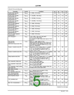
Parameter
Symbol
Conditions
= 50 mVp-p 2 MHz
min
4.9
typ
6.4
max
7.9
Unit
dB
Nonlinear emphasis
characteristics (3)
G
V
NLEMP3
IN
Measure ratio of levels of T3 and T4, difference
with G
EMP
= 50 mVp-p 500 kHz sine wave
Main linear emphasis
characteristics (1)
G
G
V
4.9
13.1
2.9
5.2
13.6
3.9
5.5
14.1
4.9
dB
dB
dB
dB
ME1
ME2
IN
Measure ratio of levels of T4 and T3, difference
with G
EMP
= 50 mVp-p 2 MHz
Main linear emphasis
characteristics (2)
V
IN
Measure ratio of levels of T4 and T3, difference
with G
EMP
Measure the amplitude at T4 when
= 15.8 mVp-p 2 MHz sine wave; compare
Detail enhancer US mode
characteristics (1)
G
ENHS1
ENHS2
V
IN
level with G
EMP
Measure the amplitude at T4 when
= 15.8 mVp-p 2 MHz sine wave in edit mode;
Detail enhancer US mode
characteristics (2)
G
0.7
1.7
2.7
V
IN
compare level with G
EMP
= 500 mVp-p white 100% video
White clipping level
Dark clipping level
L
V
186
–50
193
–45
200
–40
%
%
WC
IN
Measure white clipping level at T4
L
V
= 500 mVp-p white 100% video
IN
Measure dark clipping level at T4
DC
[PB Mode Y]
Current consumption PB
I
P
Incoming currents at pins 29 and 24 when
125
0.6
155
185
1.0
mA
ms
CC
V
= 5.0 V
CC
Dropout compensation period
T
T33A: 4 MHz, 300 mVp-p sine wave
T3A: 0.5 Vp-p video signal
DOC
T33A: time from when input went to 0 until T28A
output returned
FM demodulation voltage
FM demodulation sensitivity
V
V
= 300 mVp-p, f = 4 MHz, output voltage
0.9
1.05
0.14
1.15
V
DEM4
IN
S
V
V
= 300 mVp-p, f = 2 MHz, V
= 300 mVp-p, f = 6 MHz, V
0.11
0.17 V/MHz
DEM
IN
IN
DEM2
DEM6
Calculate S
= (V
– V
)/4
DEM
DEM2
DEM6
V
– (V
+ V
)/2
FM demodulation linearity
Carrier leakage
L
–3.5
0
+3.5
–35
%
DEM
DEM4
V
DEM2
– V
DEM6
L
=
x 100
DEM
DEM2
DEM6
CL
V
= 300 mVp-p, f = 4 MHz
Ratio between 4 MHz component of T1 and
–40
dB
IN
S
V
V
DEM
Noncorrelation detection level
V
= 500 mVp-p video signal (ramp waveform)
22
IRE
dB
CORR
IN
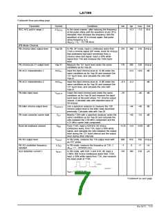
PB YNR characteristics
LP/EP (1)
GP-YNR1
GP-YNR2
GP-YNR3
= 500 mVp-p noise test signal –30 dB
2.5
1.5
1.5
4.5
IN
S/N difference with S6 on/off
PB YNR characteristics
LP/EP (2)
V
= 500 mVp-p noise test signal –30 dB
dB
dB
dB
IN
S/N difference with EDIT on/off; pin 36 low
PB YNR characteristics
SP (3)
V
= 500 mVp-p noise test signal, –30 dB
IN
S6 edit on/off S/N ratio Pin36 low
Playback through gain
G
Apply V = 0.5 Vp-p video signal to pin 3, and
IN
determine ratio between pin 28 output level and
input level
6.0
40
7.5
50
PB
Dropout detection (feedback)
level
L
T33A: 4 MHz, 300 mVp-p sine wave
T3A: 0.5 Vp-p video signal
Measure input signal level when T33A signal
drops momentarily and T28A output goes to 0
30
mVp-p
dB
DOC
Nonlinear de-emphasis
characteristics (1)
GNL
GNL
N
= white 50% video + sine wave
–6.0
–5.0
–4.0
DEEM1
IN
f = 2 MHz, 158 mVp-p
Measure I/O response, and assign output level
described above as 0 dB
Nonlinear de-emphasis
characteristics (2)
f = 2 MHz, 50 mVp-p
f = 2 MHz, 158 mVp-p
f = 2 MHz, 50 mVp-p
–9.0
–2.3
–6.0
–8.0
–1.8
–5.0
–7.0
–1.3
–4.0
dB
dB
dB
DEEM2
Double noise canceller
characteristics (1)
G
G
WNC1
Double noise canceller
characteristics (2)
WNC2
Continued on next page.
No.5472 - 4/13

 SANYO [ SANYO SEMICON DEVICE ]