LA4440
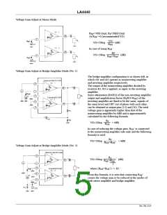
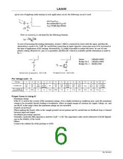
(g) In case of applying audio muting in each application circuit, the following circuit is used.
6V≤V ≤V
M
CC
Recommended V =9V
M
A =40dB (Rg=600Ω)
TT
Flow-in current I is calculated by the following formula.
O
V
M
– V
BE
R
O
I =
O
In case of increasing the muting attenuation, resistor 5.6kΩ is connected in series with the input, and then the
attenuation is made to be 55dB. Be careful that connecting an input capacitor causes pop noise to be increased at
the time of application of AC muting. Increased R , C make it possible to reduce the noise. In case of com-
O
O
pletely cutting off power IC, pin (5) is grounded, and then DC control is available and the attenuation is made to
be ∞.
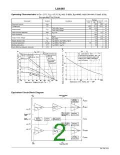
Stereo
: 20Ω≤R≤100Ω
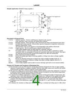
Bridge No.1 : 20Ω≤R≤100Ω
Bridge No. 2 : 0Ω≤R≤50Ω
Pin Voltage (unit : V)
Pin No.
1
2
3
4
5
6
7
8
9
10
11
12
13
14
AC
Audio
Muting
CH2
Power
GND
CH1
Power
GND
CH1
NF
CH1
NF
Pre
GND
CH2
IN
CH2
NF
CH2
BS
CH2
OUT
CH1
OUT
CH1
BS
Function pin
DC
V
CC
Pin Voltage at
quiescent mode
1.4
0.03
0
0
13.0
0.03
1.4
0
11.9
6.8
13.2
6.8
11.9
0
Proper Cares in Using IC
· Maximum ratings
If the IC is used in the vicinity of the maximum ratings, even a slight variation in conditions may cause the maximum
ratings to be exceeded, thereby leading to breakdown. Allow an ample margin of variation for supply voltage, etc. and
use the IC in the range where the maximum ratings are not exceeded.
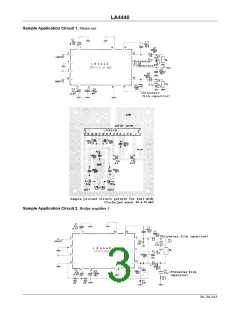
· Printed circuit board
When making the board, refer to the sample printed circuit pattern and be careful that no feedback loop is formed
between input and output.
· Oscillation preventing capacitor
Normally, a polyester film capacitor is used for 0.1µF + 4.7Ω. The capacitance value can be reduced to 0.047µF depend-
ing on the stability of the board.
· Others
Connect the radiator fin of the package to GND.
No.750–6/13

 SANYO [ SANYO SEMICON DEVICE ]