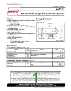
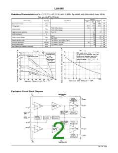
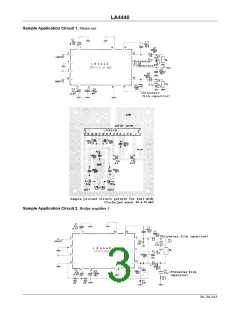
LA4440
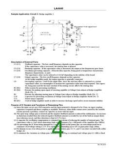
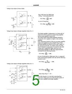
Voltage Gain Adjust at Stereo Mode
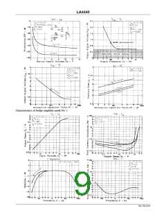
R
NF
=50Ω (typ), R =20kΩ (typ)
f
At R ’=0 (recommended VG)
NF
VG
VG=20log
(dB)
R
NF
In case of using R
’
NF
Rf
+R
VG=20log
(dB)
R
NF
’
NF
Voltage Gain Adjust at Bridge Amplifier Mode (No. 1)
· The bridge amplifier configuration is as shown left, in
which ch1 and ch2 operate as noninverting amplifier
and inverting amplifier respectively.
The output of the noninverting amplifier divided by
resistors R3, R4 is applied, as input, to the inverting
amplifier.
Since attenuation (R4/R3) of the non-inverting amplifier
output and amplification factor (R /R4+R ) of the
f
NF
inverting amplifier are fixed to be the same, signals of
the same level and 180° out of phase with each other
can be obtained at output pins (12) and (10). The total
voltage gain is apparently higher than that of the
noninverting amplifier by 6dB and is approximately
calculated by the following formula.
R
f
VG=20log
+ 6dB
R
NF
In case of reducing the voltage gain, R ’ is connected
NF
to the noninverting amplifier side only and the following
formula is used.
R
f
VG=20log
+ 6dB
R
+R
NF
’
NF
Voltage Gain Adjust at Bridge Amplifier Mode (No. 2)
R
f
VG=20log
(dB)
R
+R
NF
’
NF
2
where (R +R ’) << R5
NF
NF
From this formula, it is seen that connecting R
’
NF
causes the voltage gain to be reduced at the modes of
both stereo amplifier and bridge amplifier.
No.750–5/13

 SANYO [ SANYO SEMICON DEVICE ]