S3C4510B
INSTRUCTION SET
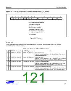
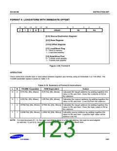
FORMAT 10: LOAD/STORE HALF-WORD
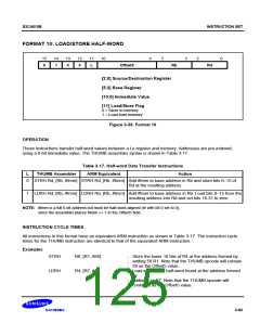
11
10
3
2
15
14
13
12
6
5
0
Rb
Rd
0
1
0
0
L
Offset5
[2:0] Source/Destination Register
[5:3] Base Register
[10:6] Immediate Value
[11] Load/Store Flag
0 = Store to memory
1 = Load from memory
Figure 3-39. Format 10
OPERATION
These instructions transfer half-word values between a Lo register and memory. Addresses are pre-indexed,
using a 6-bit immediate value. The THUMB assembler syntax is shown in Table 3-17.
Table 3-17. Half-word Data Transfer Instructions
L
THUMB Assembler
ARM Equivalent
Action
0
STRH Rd, [Rb, #Imm] STRH Rd, [Rb, #Imm] Add #Imm to base address in Rb and store bits 0–15 of
Rd at the resulting address.
1
LDRH Rd, [Rb, #Imm] LDRH Rd, [Rb, #Imm] Add #Imm to base address in Rb. Load bits 0–15 from the
resulting address into Rd and set bits 16-31 to zero.
NOTE: #Imm is a full 6-bit address but must be half-word-aligned (ie with bit 0 set to 0),
since the assembler places #Imm >> 1 in the Offset5 field.
INSTRUCTION CYCLE TIMES
All instructions in this format have an equivalent ARM instruction as shown in Table 3-17. The instruction cycle
times for the THUMB instruction are identical to that of the equivalent ARM instruction.
Examples
STRH
LDRH
R6, [R1, #56]
R4, [R7, #4]
; Store the lower 16 bits of R4 at the address formed by
; adding 56 R1. Note that the THUMB opcode will contain
; 28 as the Offset5 value.
; Load into R4 the half-word found at the address formed
by
; adding 4 to R7. Note that the THUMB opcode will
; contain 2 as the Offset5 value.
3-83

 SAMSUNG [ SAMSUNG ]