Bulletin 1489-A
Circuit Breaker
Product Description
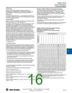
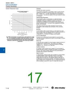
Ambient Temperature Graph
Terminals
Standard wire (cable) connection
0
1
Influence of Ambient Temperature (T)
on Load-Carrying Capacity
The standard configuration of the Bulletin 1489-A is with terminals
suitable for connection of stranded copper wire of the wire size
#18… 8 AWG (1.0 … 10 mm2). Strip length for the termination is
0.5 in. (12 mm). Terminals are shipped in the open position for ease
of installation.
1.40
Optional Ring Termination
1.30
1.20
1.10
For the Bulletin 1489-A circuit breakers, an optional terminal
configuration (suffix R) is available for use with a ring terminal. This
configuration is shipped so that the terminal screw may be
unscrewed and withdrawn for the insertion of the ring terminal at
proper connection point. The screw is then retightened to provide
proper wire termination.
2
This unique terminal may be field converted to open the wire
termination to allow standard wire termination of the converted
terminal.
1.00
0.90
3
Bus Bars
For the Bulletin 1489-A circuit breakers, UL Recognized bus bars
and UL Listed feeder terminals are available for group connection of
circuit breakers. They are available in 1-, 2-, and 3- pole
configurations for connection of multiple circuit breakers.
-20
30
40
50
-10
0
10
20
Ambient Temperature T [°C]
4
Maximum load ILat Ambient Temperature T:
I
(T) = I K (T)
n
T
L
Lock-out Attachment
The 1489-A circuit breaker can function over a wide temperature range
(-30°...+60 °C). Operation in ambient temperatures below 0 °C is based
on a non condensing atmosphere (no ice). Use the graph above or
contact your local Rockwell Automation sales office or Allen-Bradley
distributor to determine the correction factor based upon ambient
temperature.
A sturdy lock-out attachment may be added to a circuit breaker.
This lock-out may be padlocked so that the circuit breaker is locked
in the off position.
5
Shunt Trip
A shunt trip may be added to a circuit breaker to allow the device to
be tripped from a remote source. One version is for tripping
voltages of 12…110V AC (12…60V DC) and another for tripping
voltages of 110…415V AC (110…230V DC).
6
Auxiliary Contacts
An auxiliary contact module may be added to a circuit breaker to
provide pilot duty contacts to indicate the position of circuit breaker,
off or on. This contact changes state when the circuit breaker is
operated either manually or electrically.
7
Signal Contacts
A signal/auxiliary contact module may be added to a circuit breaker
to provide auxiliary contact information off and on and signal
contact pilot duty contacts. With signal contacts, the contacts
change state only when the circuit breaker changes state from On
to Off because of an electrical operation. The module contains one
signal contact, form C contact (N.O. and N.C contact with common)
and one auxiliary contact (N.O. and N.C contact with common).
8
9
10
11
12
13
www.ab.com/catalogs
Preferred availability cat. nos. are bold.
7-18
Publication A117-CA001A-EN-P

 ROCKWELL [ ROCKWELL INTERNATIONAL CORPORATION. ]