Bulletin 1489-A
Circuit Breaker
Product Description
HACR Rating
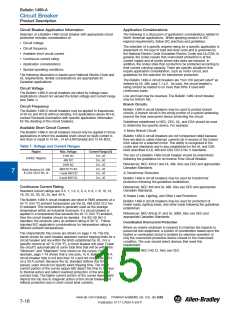
Bulletin 1489-A Ambient Temperature Derating
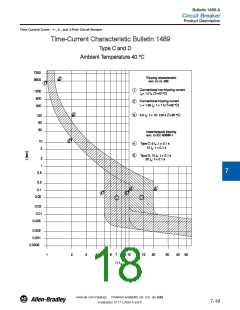
The standard tripping characteristic for Bulletin 1489-A is Type C.
Type C has a magnetic trip activated at 5…10 times the rated
current of the circuit breaker. The reference temperature for the
thermal tripping characteristics is 40 °C. The Type C characteristic
will suit most applications.
Bulletin 1489-A Circuit Breakers are rated as Heating, Air
Conditioning and Refrigeration circuit breakers as defined by UL
489, paragraph 6.7 and may used in this type of application.
0
SWD Rating
The Bulletin 1489 breakers (0.5 … 20 A) are rated as SWD and as
such may be applied to switch fluorescent lighting loads up to their
current and voltage maximum.
In rare occurrences when the Type C characteristic does not fully
meet the application, the following additional magnetic trip
characteristic is available:
1
Current Limiting
Type D allows for transients approximately twice as high as the
standard Type C.
Bulletin 1489-A Circuit Breakers are rated as current limiting circuit
breakers as defined by UL 489, paragraph 8.6.
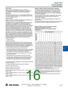
Use the following table and graph to determine the current rating for
the breaker if the ambient is significantly different than 40 °C.
2
The Bulletin 1489-A line features the ability to achieve short circuit
interruptions far more effectively than conventional breakers. In
conventional circuit breakers, the short circuit interruption time
required is approximately one or two half cycles of an AC sine wave.
When the contacts open, the resulting arc continues to burn until
the current level passes through zero. The arc may re-ignite
because of the insufficient width of the contact gap. The current
that flows until the arc is extinguished produces a heating effect
proportional to the I2t value (let-through-energy) of the fault current.
Bulletin 1489-A Ambient Temperature Derating
Calibration Temperature 40º C (UL)
Application below 0º C is for non-condensing
atmosphereꢁ
3
Ambient Temperature (°C)
The Bulletin 1489-A device is designed to substantially reduce the
amount of let-through-current and the resulting let-through-energy
that can damage protected components. The Bulletin 1489 has the
ability to interrupt short circuit current within the first half cycle of
the fault. Limiting let-through current and energy will protect against
the harmful effects of overcurrent and is focused primarily on
avoiding the following:
4
5
ꢀ Excessive Heat
ꢀ Mechanical Damage
-25 -20 -10
0
10
20
30
35
40
45
50
55
Both of these factors are proportional to the square of the current.
Thermal energy is proportional to the square of the RMS value and
magnetic forces are proportional to the square of the peak value.
The most effective way to provide protection is to substantially limit
let-through-energy. This provides the following advantages
0.5 0.6 0.6 0.6 0.6 0.6 0.5 0.5 0.5 0.50 0.5 0.5 0.5
1.0 1.3 1.2 1.2 1.2 1.1 1.1 1.0 1.0 1.0 1.0 1.0 0.9
1.5 1.9 1.9 1.8 1.7 1.7 1.6 1.6 1.5 1.5 1.5 1.4 1.4
2.0 2.5 2.5 2.4 2.3 2.2 2.2 2.1 2.0 2.0 2.0 1.9 1.9
3.0 3.8 3.7 3.6 3.5 3.4 3.2 3.1 3.1 3.0 2.9 2.9 2.8
4.0 5.0 5.0 4.8 4.6 4.5 4.3 4.2 4.1 4.0 3.9 3.8 3.8
5.0 6.3 6.2 6.0 5.8 5.6 5.4 5.2 5.1 5.0 4.9 4.8 4.7
6.0 7.5 7.4 7.2 7.0 6.7 6.5 6.2 6.1 6.0 5.9 5.8 5.6
7.0 8.8 8.7 8.4 8.1 7.8 7.6 7.3 7.1 7.0 6.9 6.7 6.6
8.0 10.0 9.9 9.6 9.3 9.0 8.6 8.3 8.2 8.0 7.8 7.7 7.5
10.0 12.6 12.4 12.0 11.6 11.2 10.8 10.4 10.2 10 9.8 9.6 9.4
13.0 16.3 16.1 15.6 15.1 14.6 14.0 13.5 13.3 13 12.7 12.5 12.2
15.0 18.8 18.6 18.0 17.4 16.8 16.2 15.6 15.3 15 14.7 14.4 14.1
16.0 20.1 19.8 19.2 18.6 17.9 17.3 16.6 16.3 16 15.7 15.4 15.0
20.0 25.1 24.8 24.0 23.2 22.4 21.6 20.8 20.4 20 19.6 19.2 18.8
25.0 31.4 31.0 30.0 29.0 28.0 27.0 26.0 25.5 25 24.5 24.0 23.5
30.0 37.7 37.2 36.0 34.8 33.6 32.4 31.2 30.6 30 29.4 28.8 28.2
32.0 40.2 39.7 38.4 37.1 35.8 34.6 33.3 32.6 32 31.4 30.7 30.1
40.0 43.9 43.4 42.0 40.6 39.2 37.8 36.4 35.7 35 34.3 33.6 32.9
6
ꢀ Far less damage at the location of the short circuit.
7
ꢀ Fast electric separation of a faulty unit from the system, especially
power supplies connected in parallel that are switched off when
the voltage of the power bus drops below a certain level.
ꢀ Far less wear on the miniature circuit breaker itself. This means
more safe interruptions.
8
ꢀ Better protection of all components in the short circuit path.
ꢀ Far wider range of selective action when used with an upstream
protective device. (No nuisance shut downs from feeder line
interruptions, causing a blackout in all connected branches.)
9
The following values are applicable to the whole product range with
frequency of 50/60 Hz.
The values were derived from worst case V AC testing of:
D trip 40 A, 240V AC @ 10 kA
10
11
12
13
ꢁ Care should be taken for application below 0 °C. These devices are not
certified to operate correctly in the presence of ice.
All other specifications for standard Bulletin 1489-A products remain
unchanged.
The ambient temperature derating applies to applications of the device as an
IEC Miniature Circuit Breaker (MCB), following 60 947-2 and as Circuit
Breaker to UL489/CSA 22.2 No 5..
Ambient temperature refers to the free air temperature in contact with the
1489 device
D trip 32 A, 480Y/277V AC @ 10 kA
D trip 20 A, 480Y/277V AC @ 14 kA
Current-Limiting at 240V / 10 kA1p, 2p, 3p I2t = 43 kA²s and I
peak = 6.2 kA
Current-Limiting at 480Y/277V / 10 kA 1p, 2p, 3p I2t = 60 kA²s and
I peak = 6.2 kA
Current-Limiting at 480Y/277V / 14 kA 1p, 2p, 3p I2t = 65 kA²s and
I peak = 7.5 kA
www.ab.com/catalogs
Preferred availability cat. nos. are bold.
7-17
Publication A117-CA001A-EN-P

 ROCKWELL [ ROCKWELL INTERNATIONAL CORPORATION. ]