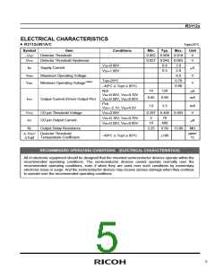
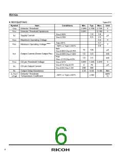
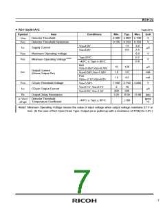
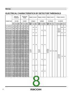
R3112x
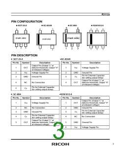
PIN CONFIGURATION
ꢀSOT-23-5
ꢀSC-82AB
ꢀSC-88A
ꢀSON1612-6
5
4
6
5
4
4
3
5
4
(mark side)
(mark side)
(mark side)
1
2
3
1
2
3
1
2
3
1
2
PIN DESCRIPTION
• SOT-23-5
•SC-82AB
Pin No. Symbol
Pin No. Symbol
Description
Description
Voltage Supply Pin
Ground Pin
Output Pin (Output “L” at
detector threshold, Output “H”
at released voltage)
1
OUT
1
VDD
2
3
VDD
Voltage Supply Pin
2
3
GND
Pin for External Capacitor
(for setting output delay)
GND
Ground Pin
CD
Output Pin (Output “L” at
detector threshold, Output “H”
at released voltage)
4
NC
No Connection
4
OUT
Pin for External Capacitor
(for setting output delay)
5
CD
• SC-88A
•SON1612-6
Pin No. Symbol
Description
Pin No. Symbol
Description
Output Pin (Output “L” at
detector threshold, Output “H”
at released voltage)
1
VDD
Voltage Supply Pin
1
OUT
2
3
NC
No Connection
Ground Pin
2
3
GND
Ground Pin
Pin for External Capacitor
(for setting output delay)
GND
CD
Pin for External Capacitor
(for setting output delay)
4
5
CD
4
NC
No Connection
Output Pin (Output “L” at
detector threshold, Output “H”
at released voltage)
OUT
5
6
GND
Ground Pin
VDD
Voltage Supply Pin
3

 RICOH [ RICOH ELECTRONICS DEVICES DIVISION ]