RT9385
Applications Information
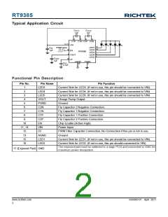
The RT9385 uses a fractional switched capacitor charge
pump to power up to five white LEDs with a programmable
current for uniform intensity. The part integrates current
sources and automatic mode selection charge pump. It
maintains the high efficiency by utilizing an x1/x1.5/x2
fractional charge pump and current sources. The small
equivalent x1 mode open loop resistance and ultra-low
dropout voltage of current source extend the operating
time of x1 mode and optimize the efficiency in white LED
applications.
Capacitors Selection
To get the better performance of the RT9385, the selection
of peripherally appropriate capacitor and value is very
important. These capacitors determine some parameters
such as input/output ripple voltage, power efficiency and
maximum supply current by charge pump. To reduce the
input and output ripple effectively, the low ESR ceramic
capacitors are recommended. For LEDdriver applications,
the input voltage ripple is more important than output
ripple. Input ripple is controlled by input capacitor CIN,
increasing the value of input capacitance can further reduce
the ripple. Practically, the input voltage ripple depends on
the power supply impedance. The flying capacitor CFLY1
and CFLY2 determine the supply current capability of the
charge pump to influence the overall efficiency of the
system. The lower value will improve efficiency. However,
it will limit the LED's current at low input voltage. For
5x25mAload over the entire input range of 2.8V to 4.5V, it
is recommended to use a 1μF ceramic capacitor on the
Input UVLO
The input operating voltage range of the LEDdriver is from
2.8V to 4.5V.An input capacitor at the VINpin could reduce
ripple voltage. It is recommended to use a ceramic 1μF or
larger capacitance as the input capacitor. The RT9385
provides an under voltage lockout (UVLO) function to
prevent it from unstable issue when startup. The UVLO
threshold of input rising voltage is set at 2V typically with
a hysteresis of 100mV.
flying capacitor CFLY1 and CFLY2
.
Soft Start
Brightness Control
The charge pump employs a soft start feature to limit the
inrush current. The soft-start circuit prevents the excessive
inrush current and input voltage drop. The soft-start clamps
the input current in a typical period of 50μs.
The RT9385 implements a PWM dimming method to
control the brightness of white LEDs. When an external
PWM signal is connected to the EN pin, brightness of
white LED is adjusted by the duty cycle. The suggested
PWM dimming frequency range is from 1kHz to 200kHz.
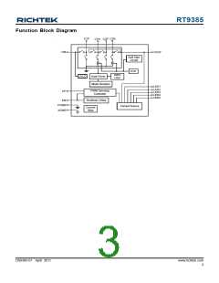
Mode Decision
The RT9385 uses a smart mode selection method to decide
the working mode for optimizing the efficiency. Mode
decision circuit senses the output and LED voltage for
up/down selection. The RT9385 automatically switches
to x1.5 or x2 mode whenever the dropout condition is
detected from the current source and returns to x1 mode
whenever the dropout condition releases.
Thermal Considerations
For continuous operation, do not exceed absolute
maximum operation junction temperature. The maximum
power dissipation depends on the thermal resistance of
IC package, PCB layout, the rate of surroundings airflow
and temperature difference between junction to ambient.
The maximum power dissipation can be calculated by
following formula :
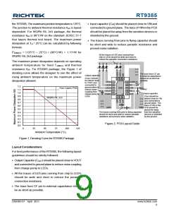
LED connection
P
D(MAX) = ( TJ(MAX) − TA ) / θJA
The RT9385 supports up to 5 white LEDs. The 5 LEDs
are connected from VIN to pin1, 2, 3, 15 and 16
respectively. If the LED is not used, the LED pin should
be connected to VIN directly.
Where TJ(MAX) is the maximum operation junction
temperature, TA is the ambient temperature and the θJA is
the junction to ambient thermal resistance.
For recommended operating conditions specification of
www.richtek.com
8
DS9385-01 April 2011

 RICHTEK [ RICHTEK TECHNOLOGY CORPORATION ]