RT9214
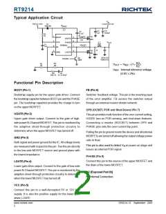
Typical Application Circuit
V
IN
+3.3V/+5V/+12V
+5V to +12V
D1
1N4148
R
BOOT
2.2
C3
1uF
C4
470uF
C2
0.1uF
R1
10
R
1
5
6
3
UGATE
Q1
2
8
BOOT
UGATE
MU
2.2
V
L1
3uH
VCC
FB
PHASE
RT9214
OUT
C1
1uF
ROCSET
7
4
OPS
R
Q2
ML
GND
LGATE
C
C6 to C8
1000uFx3
Q3
3904
Disable
>
R3
68
R3
R2
R2
32
VOUT = VREF ×(1+
)
VREF :Internal reference voltage
C5
R4
200-1k 0.1-0.33uF
(0.8V ± 2%)
Functional Pin Description
BOOT (Pin 1)
FB (Pin 6)
Bootstrap supply pin for the upper gate driver. Connect
the bootstrap capacitor between BOOT pin and the PHASE
pin. The bootstrap capacitor provides the charge to turn
on the upper MOSFET.
Switcher feedback voltage. This pin is the inverting input
of the error amplifier. FB senses the switcher output
through an external resistor divider network.
OPS (OCSET, POR and Shut-Down) (Pin 7)
UGATE (Pin 2)
This pin provides multi-function of the over-current setting,
UGATE turn-on POR sensing, and shut-down features.
Connecting a resistor (ROCSET) between OPS and
PHASE pins sets the over-current trip point.
Upper gate driver output. Connect to the gate of high-
side powerN-Channel MOSFET. This pin is monitored by
the adaptive shoot-through protection circuitry to
determine when the upper MOSFET has turned off.
Pulling the pin to ground resets the device and all external
MOSFETs are turned off allowing the output voltage power
rails to float.
GND (Pin 3)
Both signal and power ground for the IC. All voltage levels
are measured with respect to this pin. Ties the pin directly
to the low-side MOSFET source and ground plane with
the lowest impedance.
This pin is also used to detect VIN in power on stage and
issues an internal POR signal.
PHASE (Pin 8)
Connect this pin to the source of the upper MOSFET and
the drain of the lower MOSFET.
LGATE (Pin 4)
Lower gate drive output. Connect to the gate of low-side
power N-Channel MOSFET. This pin is monitored by the
adaptive shoot-through protection circuitry to determine
when the lower MOSFET has turned off.
NC [Exposed Pad (9)]
No Internal Connection.
VCC (Pin 5)
Connect this pin to a well-decoupled 5V or 12V bias
supply. It is also the positive supply for the lower gate
driver, LGATE.
DS9214-13 September 2007
www.richtek.com
2

 RICHTEK [ RICHTEK TECHNOLOGY CORPORATION ]