RT8802A
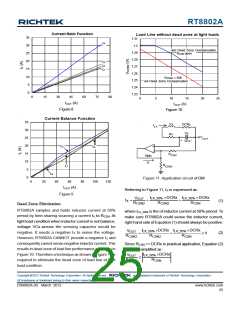
Current Ratio Function
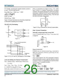
Load Line without dead zone at light loads
35
30
25
20
15
10
5
1.31
IL4
1.3
1.29
1.28
1.27
1.26
1.25
1.24
1.23
w/o Dead Zone Compensation
RCSN open
IL3
IL2
IL1
RCSN2 = 82k
w/i Dead Zone Compensation
0
0
15
30
45
60
75
90
0
5
10
15
20
25
IOUT (A)
IOUT (A)
Figure 8
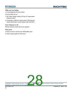
Figure 10
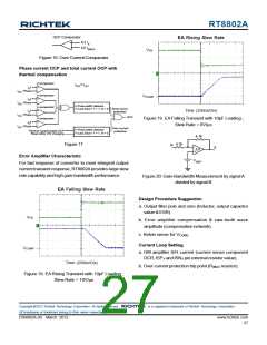
Current Balance Function
35
Lx
DCRx
I
LX
30
25
20
15
10
5
Cx
Rx
V
OUT
+
-
VCx
IL3
+
-
IL2
R
CSN
GMx
Ix
R
IL1
CSN2
IL4
0
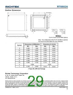
Figure 11. Application circuit of GM
0
20
40
60
80
100
120
IOUT (A)
Referring to Figure 11, IX is expressed as :
×DCRx ×DCRx
Figure 9
I
I
LX_50%
V
OUT
LX_50%
I
=
+
+
X
(1)
R
R
R
CSN
CSN2
CSN2
Dead Zone Elimination
RT8802A samples and holds inductor current at 50%
period by time-sharing sourcing a current IX to RCSN. At
light load condition when inductor current is not balance,
voltage VCx across the sensing capacitor would be
negative. It needs a negative IX to sense the voltage.
However, RT8802A CANNOT provide a negative IX and
consequently cannot sense negative inductor current. This
results in dead zone of load line performance as shown in
Figure 10. Therefore a technique as shown in Figure 11 is
required to eliminate the dead zone of load line at light
load condition.
where ILX_50% is the of inductor current at 50% period. To
make sure RT8802A could sense the inductor current,
right hand side of Equation (1) should always be positive:
I
×DCRx
I
×DCRx
R
CSN
V
LX_50%
LX_50%
OUT
(2)
+
+
≥ 0
R
R
CSN2
CSN2
Since RCSN >> DCRx in practical application, Equation (2)
could be simplified as :
ILX_50% ×DCRx
VOUT
RCSN2
≥
RCSN
Copyright 2012 Richtek Technology Corporation. All rights reserved.
©
is a registered trademark of Richtek Technology Corporation.
All brandname or trademark belong to their owner respectively.
DS8802A-09 March 2012
www.richtek.com
25

 RICHTEK [ RICHTEK TECHNOLOGY CORPORATION ]