RT8223P
Table 3. Power Up Sequencing
EN
(V)
ENC
(V)
ENTRIP1
ENTRIP2
REF
Off
VREG5 VREG3
SMPS1
SMPS2
Off
Low
Low
Low
X
X
X
X
Off
On
Off
On
Off
Off
“>2.4V”
=> High
On
Off
“>2.4V”
=> High
“>2V”
Off
Off
On
On
Off
On
Off
On
On
On
On
On
On
On
On
On
On
On
On
On
Off
Off
On
On
Off
On
Off
On
=> High
“>2.4V”
=> High
“>2V”
=> High
“>2.4V”
=> High
“>2V”
=> High
“>2.4V”
=> High
“>2V”
=> High
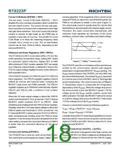
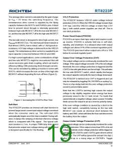
Output Voltage Setting (FBx)
where LIR is the ratio of the peak to peak ripple current to
the average inductor current.
Connect a resistor voltage-divider at the FBxpin between
VOUTx and GND to adjust the respective output voltage
between 2V and 5.5V (Figure 4). Referring to Figure 4 as
an example, choose R2 to be approximately 10kΩ, and
solve for R1 using the equation :
Find a low-loss inductor having the lowest possible DC
resistance that fits in the allotted dimensions. Ferrite cores
are often the best choice, although powdered iron is
inexpensive and can work well at 200kHz. The core must
be large enough not to saturate at the peak inductor current
(IPEAK) :
⎛
R1 ⎞
⎛
⎞
V
= V
× 1+
OUTX
FBX
⎜
⎜
⎝
⎟⎟
R2
⎠
⎝
⎠
where VFBX is 2V.
⎡
⎤
IPEAK = ILOAD(MAX) + (LIR/2)×ILOAD(MAX)
⎣
⎦
V
IN
The calculation above shall serve as a general reference.
To further improve the transient response, the output
inductance can be reduced even further. This needs to be
considered along with the selection of the output capacitor.
V
OUTx
UGATEx
PHASEx
LGATEx
R1
R2
VOUTx
FBx
Output Capacitor Selection
The capacitor value and ESR determine the amount of
output voltage ripple and load transient response. Thus,
the capacitor value must be greater than the largest value
calculated from below equations :
Figure 4. Setting VOUTX with a Resistor VoltageDivider
VOUTx
(ΔILOAD )2 ×L×(K×
+ tOFF(MIN)
)
Output Inductor Selection
V
IN
VSAG
=
The switching frequency (on-time) and operating point (%
ripple or LIR) determine the inductor value as shown in
the following equation :
⎡
⎤
⎥
⎦
⎛
⎜
⎝
⎞
⎟
⎠
VIN − VOUTx
2×COUT × VOUTx × K×
− t
OFF(MIN)
⎢
V
IN
⎣
(ΔILOAD)2 ×L
2×COUT × VOUTx
tON ×(VIN − VOUTx
LIR×ILOAD(MAX)
)
VSOAR
=
L =
DS8223P-01 June 2011
www.richtek.com
21

 RICHTEK [ RICHTEK TECHNOLOGY CORPORATION ]