RT8223P
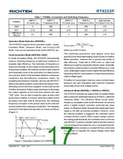
Table 1. TONSEL Connection and Switching Frequency
SMPS 1
K-Factor (μs)
SMPS 1
Frequency (kHz)
SMPS 2
K-Factor (μs)
SMPS 2
Approximate
TONSEL
Frequency (kHz) K-Factor Error (%)
GND
REF
5
200
300
4
250
375
±10
±10
3.33
2.67
VREG5 or
VREG3
2.5
400
2
500
±10
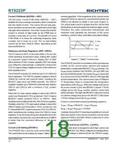
Operation Mode Selection (SKIPSEL)
(VIN − VOUT
)
The RT8223P supports three operation modes : Diode-
Emulation Mode, Ultrasonic Mode, and Forced-CCM
Mode. User can set operation mode via the SKIPSEL pin.
ILOAD (SKIP)
≈
×tON
2L
where tON is the On-time.
The switching waveforms may appear noisy and
asynchronous when light loading causesDiode-Emulation
Mode operation. However this is normal and results in
high efficiency. Trade-offs in PFM noise vs. light load
efficiency is made by varying the inductor value.Generally,
low inductor values produce a broader efficiency vs. load
curve, while higher values result in higher full-load efficiency
(assuming that the coil resistance remains fixed) and less
output voltage ripple.
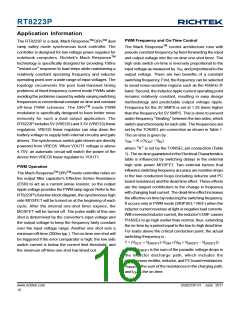
Diode-Emulation Mode (SKIPSEL=GND)
In Diode-Emulation Mode, the RT8223P automatically
reduces switching frequency at light-load conditions to
maintain high efficiency. This reduction of frequency is
achieved smoothly. As the output current decreases from
heavy-load condition, the inductor current is also reduced
and eventually comes to the point when its valley touches
zero current, which is the boundary between continuous
conduction and discontinuous conduction modes. By
emulating the behavior of diodes, the low side MOSFET
allows only partial negative current when the inductor free-
wheeling current becomes negative. As the load current
is further decreased, it takes longer and longer to discharge
the output capacitor to the level that requires the next
“ON” cycle. The on-time is kept the same as that in the
heavy-load condition. In reverse, when the output current
increases from light load to heavy-load, the switching
frequency increases to the preset value as the inductor
current reaches the continuous conduction. The transition
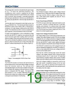
load point to the light-load operation is shown as follows
(Figure 1) :
Penalties for using higher inductor values include larger
physical size and degraded load transient response
(especially at low input-voltage levels).
Ultrasonic Mode (SKIPSEL = VREG5 or VREG3)
The RT8223P activates an uniqueDiode-Emulation Mode
with a minimum switching frequency of 25kHz, called the
Ultrasonic Mode. The Ultrasonic Mode avoids audio-
frequency modulation that would otherwise be present
when a lightly loaded controller automatically skips
pulses. In Ultrasonic Mode, the high side switch gate driver
signal is OR with an internal oscillator (>25kHz). Once
the internal oscillator is triggered, the controller enters
constant off-time control. When output voltage reaches
the setting peak threshold, the controller turns on the low
side MOSFET until the controller detects that the inductor
current dropped has below the zero-crossing threshold.
The internal timer provides a constant off-time control and
it is effective to regulate the output voltage under light
load conditions.
I
L
Slope = (V -V
IN OUT
) / L
IL, PEAK
ILoad = I
L, PEAK
/ 2
t
0
TON
Figure 1. Boundary Condition of CCM/DEM
DS8223P-01 June 2011
www.richtek.com
17

 RICHTEK [ RICHTEK TECHNOLOGY CORPORATION ]