RT6211A/B
Detailed Description
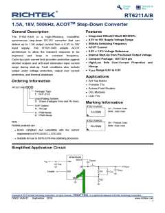
The RT6211A/B are high-performance 500kHz 1.5A
step-down regulators with internal power switches and
synchronous rectifiers. They feature an Advanced
Constant On-Time (ACOTTM) control architecture that
provides stable operation with ceramic output
capacitors without complicated external compensation,
among other benefits. The input voltage range is from
4.5V to 18V and the output is adjustable from 0.8V to
6.3V.
The proprietary ACOTTM control scheme improves
upon other constant on-time architectures, achieving
nearly constant switching frequency over line, load, and
output voltage ranges. The RT6211A/B are optimized
for ceramic output capacitors. Since there is no internal
clock, response to transients is nearly instantaneous
and inductor current can ramp quickly to maintain
output regulation without large bulk output capacitance.
Because no switching decisions are made during noisy
time periods, COT architectures are preferable in low
duty cycle and noisy applications. However, traditional
COT control schemes suffer from some disadvantages
that preclude their use in many cases. Many
applications require a known switching frequency
range to avoid interference with other sensitive circuitry.
True constant on-time control, where the on-time is
actually fixed, exhibits variable switching frequency. In
a step-down converter, the duty factor is proportional to
the output voltage and inversely proportional to the
input voltage. Therefore, if the on-time is fixed, the
off-time (and therefore the frequency) must change in
response to changes in input or output voltage.
Modern pseudo-fixed frequency COT architectures
greatly improve COT by making the one-shot on-time
proportional to VOUT and inversely proportional to VIN.
In this way, an on-time is chosen as approximately
what it would be for an ideal fixed-frequency PWM in
similar input/output voltage conditions. The result is a
big improvement but the switching frequency still varies
considerably over line and load due to losses in the
switches and inductor and other parasitic effects.
Constant On-Time (COT) Control
The heart of any COT architecture is the on-time
one-shot. Each on-time is a pre-determined “fixed”
period that is triggered by a feedback comparator. This
robust arrangement has high noise immunity and is
ideal for low duty cycle applications. After the on-time
one-shot period, there is a minimum off-time period
before any further regulation decisions can be
considered. This arrangement avoids the need to make
any decisions during the noisy time periods just after
switching events, when the switching node (LX) rises or
falls. Because there is no fixed clock, the high-side
switch can turn on almost immediately after load
transients and further switching pulses can ramp the
inductor current higher to meet load requirements with
minimal delays.
Another problem with many COT architectures is their
dependence on adequate ESR in the output capacitor,
making it difficult to use highly-desirable, small,
low-cost, but low-ESR ceramic capacitors. Most COT
architectures use AC current information from the
output capacitor, generated by the inductor current
passing through the ESR, to function in a way like a
current mode control system. With ceramic capacitors,
the inductor current information is too small to keep the
control loop stable, like a current mode system with no
current information.
Traditional current mode or voltage mode control
schemes typically must monitor the feedback voltage,
current signals (also for current limit), and internal
ramps and compensation signals, to determine when to
turn off the high-side switch and turn on the
synchronous rectifier. Weighing these small signals in a
switching environment is difficult to do just after
switching large currents, making those architectures
problematic at low duty cycles and in less than ideal
board layouts.
ACOTTM Control Architecture
Making the on-time proportional to VOUT and inversely
proportional to VIN is not sufficient to achieve good
constant-frequency behavior for several reasons. First,
voltage drops across the MOSFET switches and
inductor cause the effective input voltage to be less
than the measured input voltage and the effective
output voltage to be greater than the measured output
voltage. As the load changes, the switch voltage drops
Copyright © 2018 Richtek Technology Corporation. All rights reserved.
is a registered trademark of Richtek Technology Corporation.
DS6211A/B-07 September 2018
www.richtek.com
3

 RICHTEK [ RICHTEK TECHNOLOGY CORPORATION ]