3858 Group
FUNCTIONAL DESCRIPTION
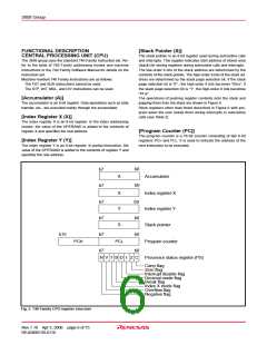
[Stack Pointer (S)]
CENTRAL PROCESSING UNIT (CPU)
The 3858 group uses the standard 740 Family instruction set. Re-
fer to the table of 740 Family addressing modes and machine
instructions or the 740 Family Software Manual for details on the
instruction set.
The stack pointer is an 8-bit register used during subroutine calls
and interrupts. This register indicates start address of stored area
(stack) for storing registers during subroutine calls and interrupts.
The low-order 8 bits of the stack address are determined by the
contents of the stack pointer. The high-order 8 bits of the stack ad-
dress are determined by the stack page selection bit. If the stack
page selection bit is “0” , the high-order 8 bits becomes “0016”. If
the stack page selection bit is “1”, the high-order 8 bits becomes
“0116”.
Machine-resident 740 Family instructions are as follows:
The FST and SLW instructions cannot be used.
The STP, WIT, MUL, and DIV instructions can be used.
[Accumulator (A)]
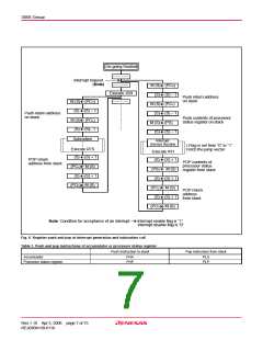
The operations of pushing register contents onto the stack and
popping them from the stack are shown in Figure 6.
Store registers other than those described in Figure 6 with pro-
gram when the user needs them during interrupts or subroutine
calls (see Table 2).
The accumulator is an 8-bit register. Data operations such as data
transfer, etc., are executed mainly through the accumulator.
[Index Register X (X)]
The index register X is an 8-bit register. In the index addressing
modes, the value of the OPERAND is added to the contents of
register X and specifies the real address.
[Program Counter (PC)]
The program counter is a 16-bit counter consisting of two 8-bit
registers PCH and PCL. It is used to indicate the address of the
next instruction to be executed.
[Index Register Y (Y)]
The index register Y is an 8-bit register. In partial instruction, the
value of the OPERAND is added to the contents of register Y and
specifies the real address.
b0
b7
A
Accumulator
b0
b0
b0
b0
b0
b7
X
Index register X
Index register Y
b7
Y
b7
S
Stack pointer
b15
b7
b7
PC
H
PC
L
Program counter
N V T B D I Z C
Processor status register (PS)
Carry flag
Zero flag
Interrupt disable flag
Decimal mode flag
Break flag
Index X mode flag
Overflow flag
Negative flag
Fig. 5 740 Family CPU register structure
Rev.1.10 Apr 3, 2006 page 6 of 75
REJ03B0139-0110

 RENESAS [ RENESAS TECHNOLOGY CORP ]