3858 Group
b7
b0
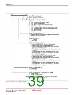
Timer Z2 mode register
(TZ2M : address 002B16
)
Timer Z2 operating mode bits
b2b1b0
0 0 0 : Timer/Event counter mode
0 0 1 : Pulse output mode
0 1 0 : Pulse period measurement mode
0 1 1 : Pulse width measurement mode
1 0 0 : Programmable waveform generating mode
1 0 1 : Programmable one-shot generating mode
1 1 0 : Not available
1 1 1 : Not available
Timer Z2 write control bit
0 : Writing data to both latch and timer simultaneously
1 : Writing data only to latch
Output level latch
0 : “L” output
1 : “H” output
CNTR active edge switch bit
3
0 : •Event counter mode: Count at rising edge
•Pulse output mode: Start outputting “H”
•Pulse period measurement mode: Measurement
between two falling edges
•Pulse width measurement mode: Measurement of
“H” term
•Programmable one-shot generating mode: After
start outputting “L”, “H” one-shot pulse generated
•Interrupt at falling edge
1 : •Event counter mode: Count at falling edge
•Pulse output mode: Start outputting “L”
•Pulse period measurement mode: Measurement
between two rising edges
•Pulse width measurement mode: Measurement of
“L” term
•Programmable one-shot generating mode: After
start outputting “H”, “L” one-shot pulse generated
•Interrupt at rising edge
Timer Z2 count stop bit
0 : Count start
1 : Count stop
Timer/Event counter mode switch bit (Note)
0 : Timer mode
1 : Event counter mode
Note: When selecting the modes except the timer/event
counter mode, set “0” to this bit.
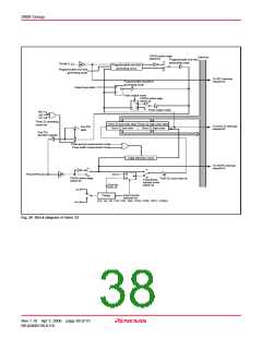
Fig. 29 Structure of timer Z2 mode register
Rev.1.10 Apr 3, 2006 page 39 of 75
REJ03B0139-0110

 RENESAS [ RENESAS TECHNOLOGY CORP ]