455A Group
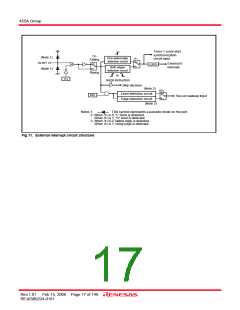
Timer 1 count start
synchronization
circuit input
I12
Falling
(Note 1)
D9 /INT
One-sided edge
detection circuit
I11
0
External 0
0
EXF0
1
Both edges
detection circuit
interrupt
1
(Note 1)
Rising
or
I13
SNZI0 instruction
Skip decision
(Note 2)
K21
0
Level detection circuit
Edge detection circuit
K20
Key-on wakeup input
1
(Note 3)
Notes 1:
This symbol represents a parasitic diode on the port.
2: When I12 is 0, “L” level is detected.
When I12 is 1, “H” level is detected.
3: When I12 is 0, falling edge is detected.
When I12 is 1, rising edge is detected.
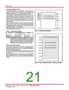
Fig 11. External interrupt circuit structure
Rev.1.01 Feb 15, 2008 Page 17 of 146
REJ03B0224-0101

 RENESAS [ RENESAS TECHNOLOGY CORP ]