For NMI interrupts while flash memory is being programmed or erased, these malfunction and
runaway problems can be prevented by using the RAM overlap function with the settings
described below.
1. Do not store the NMI interrupt-handling routine*3 in the flash memory area (H'0000 to
H'7FFF). Store it elsewhere (in RAM, for example).
2. Set the NMI interrupt vector in address H'FC06 in RAM (corresponding to H'0006 in flash
memory).
3. After the above settings, set both the RAMS and RAM0 bits to 1 in WSCR.*4
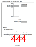
Due to the setting of step 3, if an interrupt signal is input while 12 V is applied to the FVPP pin, the
RAM overlap function is enabled and part of the RAM (H'FC00 to H'FC7F) is overlapped onto the
small-block area of flash memory (H'0000 to H'007F). As a result, when an interrupt is input, the
vector is read from RAM, not flash memory, so the interrupt is handled normally even if flash
memory is being programmed or erased. This can prevent malfunction and runaway.
Notes: *1 When the interrupt mask bit (I) of the condition control register (CCR) is set to 1, all
interrupts except NMI are masked. For details see (2) in section 2.2.2, Control
Registers.
*2 The vector table might not be read correctly for one of the following reasons:
•
If flash memory is read while it is being programmed or erased (while the P or E bit
of FLMCR is set), the correct value cannot be read.
•
If no value has been written for the NMI entry in the vector table yet, NMI
exception handling will not be executed correctly.
*3 This routine should be programmed so as to prevent microcontroller runaway.
*4 For details on WSCR settings, see section 19.2.4, Wait-State Control Register.
Notes on Interrupt Handling in Boot Mode: In boot mode, the settings described above
concerning NMI interrupts are carried out, and NMI interrupt handling (but not other interrupt
handling) is enabled while the boot program is executing. Note the following points concerning
the user program.
•
If interrupt handling is required
Load the NMI vector (H'FB80) into address H'FC06 in RAM (the 38th byte of the
transferred user program should be H'FB80).
The interrupt handling routine used by the boot program is stored in addresses H'FB80 to
H'FB8F in RAM. Make sure that the user program does not overwrite this area.
•
If interrupt handling is not required
Since the RAMS and RAM0 bits remain set to 1 in WSCR, make sure that the user program
disables the RAM overlap by clearing the RAMS and RAM0 bits both to 0.
412

 RENESAS [ RENESAS TECHNOLOGY CORP ]