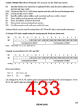
Sample Multiple-Block Erase Program: This program uses the following registers.
R0: Specifies blocks to be erased (set as explained below), and also stores address used in
prewrite and erase-verify.
R1H: Used to test bits 8 to 11 of R0 stores register read data, and also used for dummy write.
R1L: Used to test bits 0 to 11 of R0.
R2: Specifies address where address used in prewrite and erase-verify is stored.
R3: Stores address used in prewrite and erase-verify.
R4: Stores last address of block to be erased.
R5: Sets prewrite and erase timing loop counters.
R6L: Used for prewrite-verify and erase-verify fail count.
Arbitrary blocks can be erased by setting bits in R0. Write R0 with a word transfer instruction.
A bit map of R0 and a sample setting for erasing specific blocks are shown next.
Bit
R0
15 14 13 12 11 10
LB3 LB2 LB1 LB0 SB7 SB6 SB5 SB4 SB3 SB2 SB1 SB0
Corresponds to EBR1 Corresponds to EBR2
9
8
7
6
5
4
3
2
1
0
—
—
—
—
Note: Clear bits 15, 14, 13, and 12 to 0.
Example: to erase blocks LB2, SB7, and SB0
Bit
R0
15 14 13 12 11 10
9
8
7
6
5
4
3
2
1
0
—
—
—
—
LB3 LB2 LB1 LB0 SB7 SB6 SB5 SB4 SB3 SB2 SB1 SB0
Corresponds to EBR1 Corresponds to EBR2
Setting
0
0
0
0
0
1
0
0
1
0
0
0
0
0
0
1
R0 is set as follows:
MOV.W
MOV.W
#H'0481,R0
R0, @EBR1
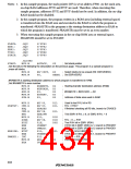
The setting of #a, #b, #c, #d, and #e values in the program depends on the clock frequency. Set #a,
#b, #c, #d, and #e values according to tables 19.9 (1), (2), and 19.10.
403

 RENESAS [ RENESAS TECHNOLOGY CORP ]