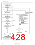
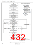
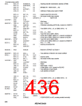
Flowchart for Erasing Multiple Blocks
Start
Notes: *1 Program all addresses to be
erased by following the
Set erase block registers
(set bits of blocks to be erased to 1)
prewrite flowchart.
*2 Set the watchdog timer
overflow interval to the value
indicated in table 19.10.
*3 For the erase-verify dummy
write, write H'FF with a byte
transfer instruction.
Write 0 data to all addresses to be
erased (prewrite)*1
n = 1
Enable watchdog timer*2
*4 Read the data to be verified
with a byte transfer instruction.
When erasing two or more
blocks, clear the bits of erased
blocks in the erase block
Select erase mode (E bit = 1 in FLMCR)
register, so that only unerased
blocks will be erased again.
Wait (X) ms *5
Clear E bit
*5 X:
10 ms
Erasing ends
tVS1: 4 µs or more
tVS2: 2 µs or more
Disable watchdog timer
N:
3000
Select erase-verify mode
(EV bit = 1 in FLMCR)
Wait (tVS1) µs*5
Set top address of block as
verify address
Dummy write to verify address*3
(flash memory latches address)
Erase-verify
next block
Wait (tVS2) µs*5
Erase-verify next block
Verify*4
No go
(read data H'FF?)
OK
No
No
Last address
in block?
All erased blocks
Address + 1 → address
verified?
Yes
Yes
Clear EBR bit of erased block
No
All erased blocks
verified?
Yes
Clear EV bit
No
All blocks erased?
(EBR1 = EBR2 = 0?)
No
n ≥ N?*5
Yes
Yes
Erase error
n + 1 → n
End of erase
Figure 19.11 Multiple-Block Erase Flowchart
402

 RENESAS [ RENESAS TECHNOLOGY CORP ]