19.4.6
Erasing Flowchart and Sample Program
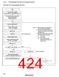
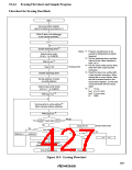
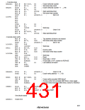
Flowchart for Erasing One Block
Start
Set erase block register
(set bit of block to be erased to 1)
Write 0 data in all addresses
to be erased (prewrite)*1
n = 1
Enable watchdog timer*2
Notes: *1 Program all addresses to be
erased by following the prewrite
flowchart.
Select erase mode
(E bit = 1 in FLMCR)
*2 Set the watchdog timer overflow
interval to the value indicated in
table 19.10.
Wait (x) ms *5
Clear E bit
*3 For the erase-verify dummy write,
Erasing ends
write H'FF with a byte transfer
instruction.
*4 Read the data to be verified with
a byte transfer instruction. When
erasing two or more blocks, clear
the bits of erased blocks in the
erase block registers, so that only
unerased blocks will be erased
again.
Disable watchdog timer
Set top address in block
as verify address
Select erase-verify mode
(EV bit = 1 in FLMCR)
*5 x:
10 ms
t
t
N:
VS1: 4 µs or more
VS2: 2 µs or more
Wait (tVS1) µs *5
3000
Dummy write to verify address*3
(flash memory latches address)
Wait (tVS2) µs *5
No go
Verify*4 (read data H'FF?)
OK
Erase-verify ends
No
Clear EV bit
No
Address + 1 → address
Last address?
n ≥ N? *5
Yes
n + 1 → n
Clear EV bit
Yes
Clear erase block register
(clear bit of erased block to 0)
Erase error
End of block erase
Figure 19.9 Erasing Flowchart
397

 RENESAS [ RENESAS TECHNOLOGY CORP ]