13.3.8
Sample Flowcharts
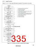
Figures 13.12 to 13.15 show typical flowcharts for using the I2C bus interface in each mode.
Start
Initialize
1. Test the status of the SCL and SDA lines.
Read BBSY in ICSR
1
2. Select master transmit mode.
No
3. Generate a start condition.
BBSY = 0?
Yes
4. Set transmit data for the first byte (slave address + R/W).
5. Wait for 1 byte to be transmitted.
2
3
4
5
Set MST = 1 and
TRS = 1 in ICCR
6. Test for acknowledgement by the designated slave device.
7. Set transmit data for the second and subsequent bytes.
8. Wait for 1 byte to be transmitted.
Write BBSY = 1
and SCP = 0 in ICSR
9. Test for end of transfer.
Write transmit data in ICDR
Read IRIC in ICSR
IRIC = 1?
10. Generate a stop condition.
No
Yes
Clear IRIC in ICSR
Read ACKB in ICSR
6
No
No
ACKB = 0?
Yes
Master receive mode
Transmit mode?
Yes
7
8
Write transmit data in ICDR
Read IRIC in ICSR
IRIC = 1?
No
Yes
Clear IRIC in ICSR
Read ACKB in ICSR
9
No
End of transmission
(ACKB = 1)?
Yes
10
Write BBSY = 0
and SCP = 0 in ICSR
End
Figure 13.12 Flowchart for Master Transmit Mode (Example)
305

 RENESAS [ RENESAS TECHNOLOGY CORP ]