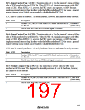
Bit 5—Input Capture Flag C (ICFC): This status bit is set to 1 to flag input of a rising or falling
edge of FTIC as selected by the IEDGC bit. When BUFEA = 0, this indicates capture of the FRC
count in ICRC. When BUFEA = 1, however, the FRC count is not captured, so ICFC becomes
simply an external interrupt flag. In other words, the buffer mode frees FTIC for use as a general-
purpose interrupt signal (which can be enabled or disabled by the ICICE bit).
ICFC must be cleared by software. It is set by hardware, however, and cannot be set by software.
Bit 5: ICFC
Description
0
To clear ICFC, the CPU must read ICFC after it has been set to 1, then write a
0 in this bit.
(Initial value)
1
This bit is set to 1 when an FTIC input signal is received.
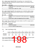
Bit 4—Input Capture Flag D (ICFD): This status bit is set to 1 to flag input of a rising or falling
edge of FTID as selected by the IEDGD bit. When BUFEB = 0, this indicates capture of the FRC
count in ICRD. When BUFEB = 1, however, the FRC count is not captured, so ICFD becomes
simply an external interrupt flag. In other words, the buffer mode frees FTID for use as a general-
purpose interrupt signal (which can be enabled or disabled by the ICIDE bit).
ICFD must be cleared by software. It is set by hardware, however, and cannot be set by software.
Bit 4: ICFD
Description
0
To clear ICFD, the CPU must read ICFD after it has been set to 1, then write a
0 in this bit.
(Initial value)
1
This bit is set to 1 when an FTID input signal is received.
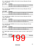
Bit 3—Output Compare Flag A (OCFA): This status flag is set to 1 when the FRC value
matches the OCRA value. This flag must be cleared by software. It is set by hardware, however,
and cannot be set by software.
Bit 3: OCFA
Description
0
To clear OCFA, the CPU must read OCFA after it has been set to 1, then write
a 0 in this bit.
(Initial value)
1
This bit is set to 1 when FRC = OCRA.
167

 RENESAS [ RENESAS TECHNOLOGY CORP ]